

Question: Fig . 1 : Closed loop temperature control of a Heat Exchanger Tasks: Section - A: Dynamic performance and control system design of the heat
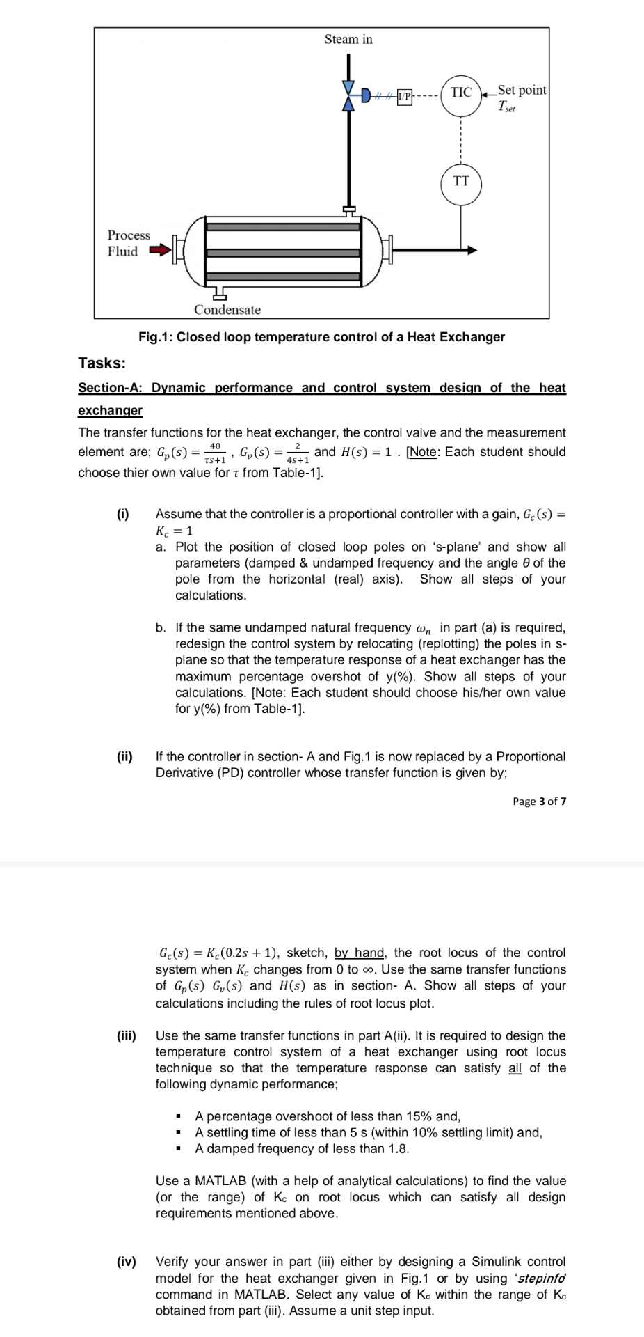
Fig: Closed loop temperature control of a Heat Exchanger
Tasks:
SectionA: Dynamic performance and control system design of the heat exchanger
The transfer functions for the heat exchanger, the control valve and the measurement element are; and Note: Each student should choose thier own value for from Table
i Assume that the controller is a proportional controller with a gain,
a Plot the position of closed loop poles on splane' and show all parameters damped & undamped frequency and the angle of the pole from the horizontal real axis Show all steps of your calculations.
b If the same undamped natural frequency in part a is required, redesign the control system by relocating replotting the poles in splane so that the temperature response of a heat exchanger has the maximum percentage overshot of Show all steps of your calculations. Note: Each student should choose hisher own value for from Table
ii If the controller in section A and Fig. is now replaced by a Proportional Derivative PD controller whose transfer function is given by;
Page of
sketch, by hand, the root locus of the control system when changes from to Use the same transfer functions of and as in section A Show all steps of your calculations including the rules of root locus plot.
iii Use the same transfer functions in part ii It is required to design the temperature control system of a heat exchanger using root locus technique so that the temperature response can satisfy all of the following dynamic performance;
A percentage overshoot of less than and,
A settling time of less than s within settling limit and,
A damped frequency of less than
Use a MATLAB with a help of analytical calculations to find the value or the range of on root locus which can satisfy all design requirements mentioned above.
iv Verify your answer in part iii either by designing a Simulink control model for the heat exchanger given in Fig. or by using 'stepinfo' command in MATLAB. Select any value of within the range of obtained from part iii Assume a unit step input.
Step by Step Solution
There are 3 Steps involved in it
1 Expert Approved Answer
Step: 1 Unlock

Question Has Been Solved by an Expert!
Get step-by-step solutions from verified subject matter experts
Step: 2 Unlock
Step: 3 Unlock