

Question: Fig. 3(b). 4. For the shown in Fig. 4(a) the generators are connected at the four buses, while the loads are at [5] buses
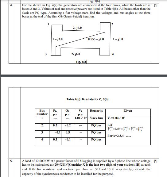
Fig. 3(b). 4. For the shown in Fig. 4(a) the generators are connected at the four buses, while the loads are at [5] buses 2 and 3. Values of real and reactive powers are listed in Table 4(b). All buses other than the slack are PQ type. Assuming a flat voltage start, find the voltages and bus angles at the three buses at the end of the first GS(Gauss-Seidel) iteration. 2-j6.0 1-j3.0 0.555-12.0 1-j3.0 3 2-j6.0 Fig. 4(a) Table 4(b): Bus data for Q. 3(b) Bus QL V Remarks number p.u. p.u. 1 - 1.04 20 Slack bus Vi 1.040 2 -0.2 -- PQ bus Let V"=120=V = V = V 3 -0.1 0.5 PQ bus For k=2,3,4, 4 0.3 -0.1 PQ bus A load of 12,000KW at a power factor of 0.8 lagging is supplied by a 3-phase line whose voltage 151 has to be maintained at (20+X)KV[Consider X is the last two digit of your student ID] at each end. If the line resistance and reactance per phase are 50 and 10 respectively, calculate the capacity of the synchronous condenser to be installed for the purpose. Pk p.u - 0.5 Given
Step by Step Solution
3.28 Rating (154 Votes )
There are 3 Steps involved in it
Date 01joza f scution 1jos 005j015 815 ... View full answer

Get step-by-step solutions from verified subject matter experts