

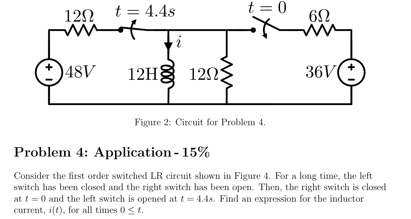
Question: Figure 2 : Circuit for Problem 4 . Problem 4 : Application - 1 5 % Consider the first order switched LR circuit shown
Figure : Circuit for Problem
Problem : Application
Consider the first order switched LR circuit shown in Figure For a long time, the left switch has been closed and the right switch has been open. Then, the right switch is closed at t and the left switch is opened at tmathrm~s Find an expression for the inductor current, it for all times leq t
Step by Step Solution
There are 3 Steps involved in it
1 Expert Approved Answer
Step: 1 Unlock

Question Has Been Solved by an Expert!
Get step-by-step solutions from verified subject matter experts
Step: 2 Unlock
Step: 3 Unlock