

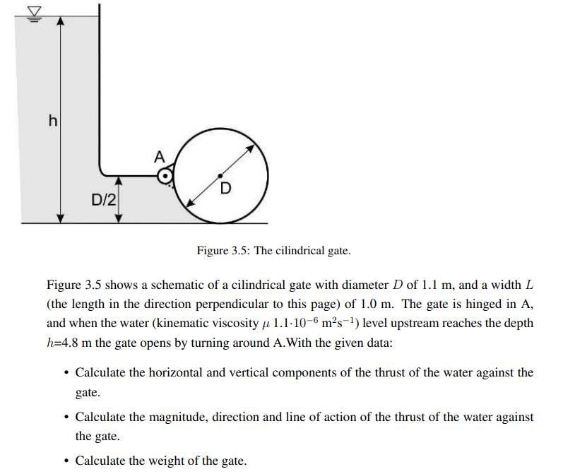
Question: Figure 3 . 5 : The cilindrical gate. Figure 3 . 5 shows a schematic of a cilindrical gate with diameter D of 1 .
Figure : The cilindrical gate.
Figure shows a schematic of a cilindrical gate with diameter of and a width
the length in the direction perpendicular to this page of The gate is hinged in A
and when the water kinematic viscosity level upstream reaches the depth
the gate opens by turning around A With the given data:
Calculate
The horizontal component of the water thrust : N
The vertical component of the water thrust : N
The total magnitude of the water thrust : N
The angle of action from the horizontal plane : Degrees
The weight of the gate : N
Step by Step Solution
There are 3 Steps involved in it
1 Expert Approved Answer
Step: 1 Unlock

Question Has Been Solved by an Expert!
Get step-by-step solutions from verified subject matter experts
Step: 2 Unlock
Step: 3 Unlock