

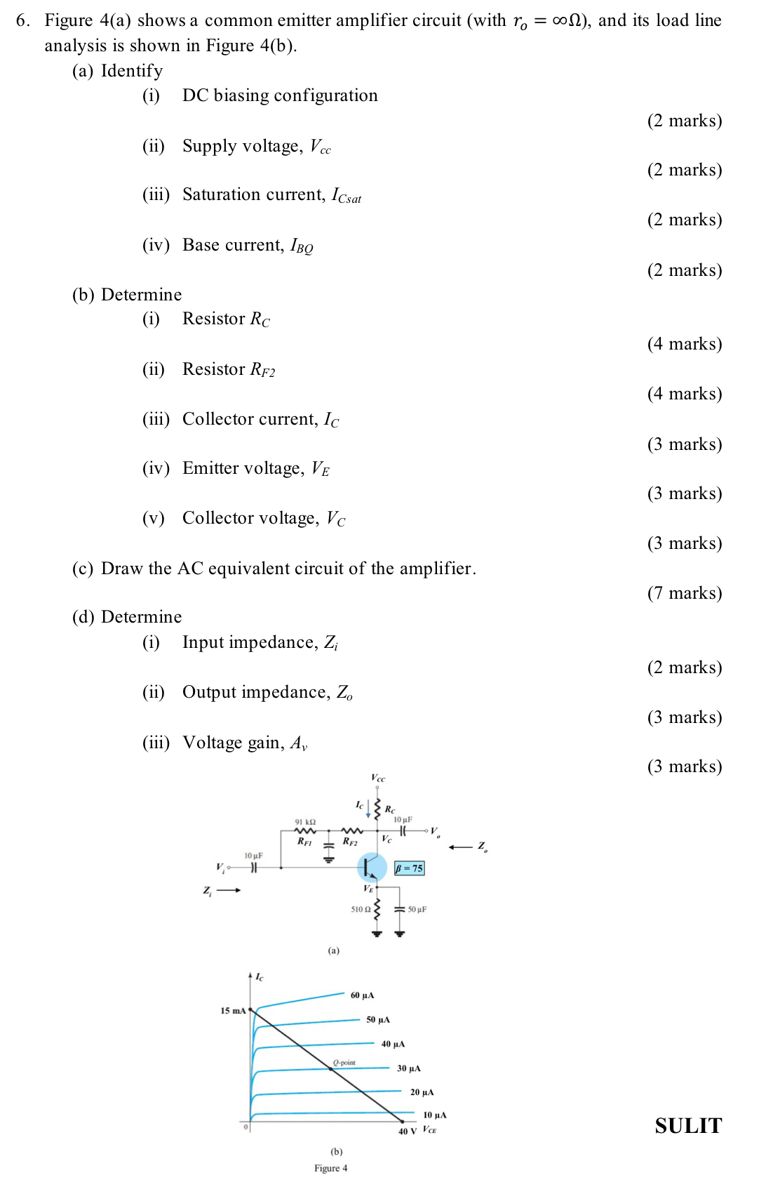
Question: Figure 4 ( a ) shows a common emitter amplifier circuit ( with r o = ) , and its load line analysis is shown
Figure a shows a common emitter amplifier circuit with and its load line analysis is shown in Figure b
a Identify
i DC biasing configuration
ii Supply voltage,
marks
iii Saturation current,
marks
iv Base current,
marks
marks
b Determine
i Resistor
marks
ii Resistor
marks
iii Collector current,
marks
iv Emitter voltage,
marks
v Collector voltage,
marks
c Draw the AC equivalent circuit of the amplifier.
marks
d Determine
i Input impedance,
marks
ii Output impedance,
marks
iii Voltage gain,
marks
SULIT
Figure a shows a common emitter amplifier circuit with and its load line analysis is shown in Figure b
a Identify
i DC biasing configuration
ii Supply voltage,
marks
iii Saturation current,
marks
iv Base current,
marks
marks
b Determine
i Resistor
marks
ii Resistor
marks
iii Collector current,
marks
iv Emitter voltage,
marks
v Collector voltage,
marks
c Draw the AC equivalent circuit of the amplifier.
marks
d Determine
i Input impedance,
marks
ii Output impedance,
marks
iii Voltage gain,
marks
Step by Step Solution
There are 3 Steps involved in it
1 Expert Approved Answer
Step: 1 Unlock

Question Has Been Solved by an Expert!
Get step-by-step solutions from verified subject matter experts
Step: 2 Unlock
Step: 3 Unlock