

Question: Figure 4 : Circuit tor Problem 4 . Problem 4 : Application - 1 5 % Consider the circuit shown in Figure 4 where Z
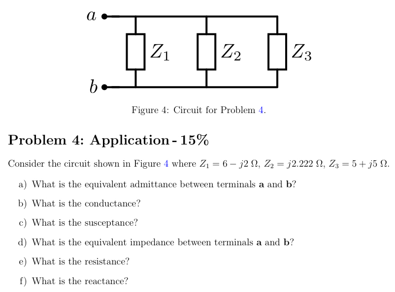
Figure : Circuit tor Problem
Problem : Application
Consider the circuit shown in Figure where
a What is the equivalent admittance between terminals a and
b What is the conductance?
c What is the susceptance?
d What is the equivalent impedance between terminals a and
e What is the resistance?
f What is the reactance?
Step by Step Solution
There are 3 Steps involved in it
1 Expert Approved Answer
Step: 1 Unlock

Question Has Been Solved by an Expert!
Get step-by-step solutions from verified subject matter experts
Step: 2 Unlock
Step: 3 Unlock