

Question: Figure 9 . 2 6 shows the cross - frequency response ( receptance ) locus for a lathe between the cutting - force direction and
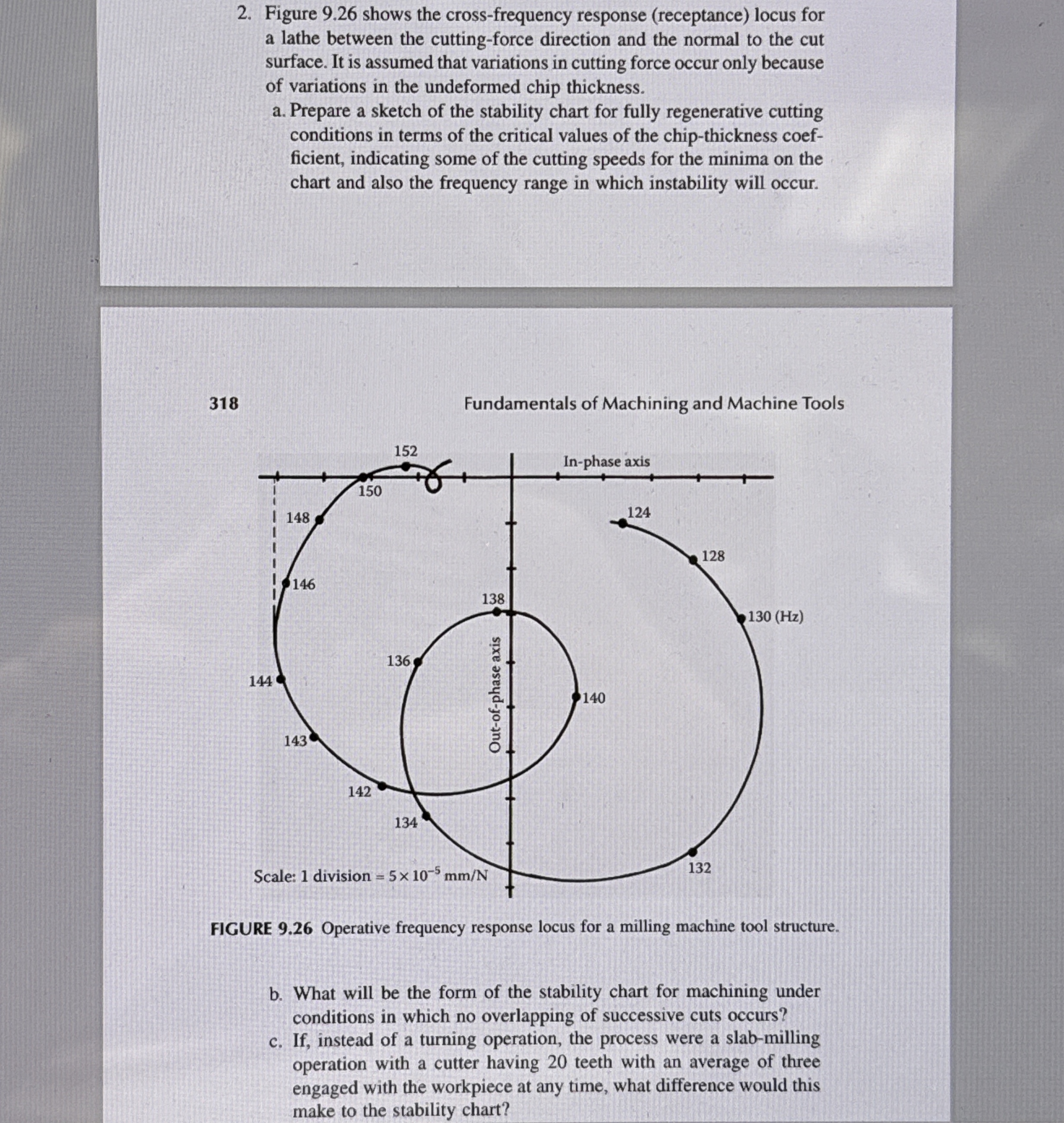
Figure shows the crossfrequency response receptance locus for a lathe between the cuttingforce direction and the normal to the cut surface. It is assumed that variations in cutting force occur only because of variations in the undeformed chip thickness.
a Prepare a sketch of the stability chart for fully regenerative cutting conditions in terms of the critical values of the chipthickness coefficient, indicating some of the cutting speeds for the minima on the chart and also the frequency range in which instability will occur.
Fundamentals of Machining and Machine Tools
FIGURE Operative frequency response locus for a milling machine tool structure.
b What will be the form of the stability chart for machining under conditions in which no overlapping of successive cuts occurs?
c If instead of a turning operation, the process were a slabmilling operation with a cutter having teeth with an average of three engaged with the workpiece at any time, what difference would this make to the stability chart?
Step by Step Solution
There are 3 Steps involved in it
1 Expert Approved Answer
Step: 1 Unlock

Question Has Been Solved by an Expert!
Get step-by-step solutions from verified subject matter experts
Step: 2 Unlock
Step: 3 Unlock