

Question: Figure (a) shows the schematic plan view for a differential mobile robot. The robot is designed to carry a large battery, a camera and
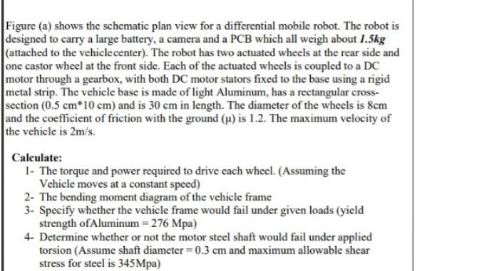
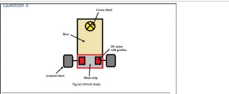
Figure (a) shows the schematic plan view for a differential mobile robot. The robot is designed to carry a large battery, a camera and a PCB which all weigh about 1.5kg (attached to the vehicle center). The robot has two actuated wheels at the rear side and one castor wheel at the front side. Each of the actuated wheels is coupled to a DC motor through a gearbox, with both DC motor stators fixed to the base using a rigid metal strip. The vehicle base is made of light Aluminum, has a rectangular cross- section (0.5 cm*10 cm) and is 30 cm in length. The diameter of the wheels is 8cm and the coefficient of friction with the ground (u) is 1.2. The maximum velocity of the vehicle is 2m/s. Calculate: 1- The torque and power required to drive each wheel. (Assuming the Vehicle moves at a constant speed) 2- The bending moment diagram of the vehicle frame 3- Specify whether the vehicle frame would fail under given loads (yield strength of Aluminum = 276 Mpa) 4- Determine whether or not the motor steel shaft would fail under applied torsion (Assume shaft diameter = 0.3 cm and maximum allowable shear stress for steel is 345Mpa) Question 3 Base Actuated wheel Castor wheel DC motor with gearbox 0,00 Metal strip Fig.(a) Vehicle body
Step by Step Solution
There are 3 Steps involved in it

Get step-by-step solutions from verified subject matter experts