

Question: Figure Q2 in Appendix B illustrates a process flow diagram of benzene production via hydrodealkylation of toluene. Refer to the provided process description and Figure
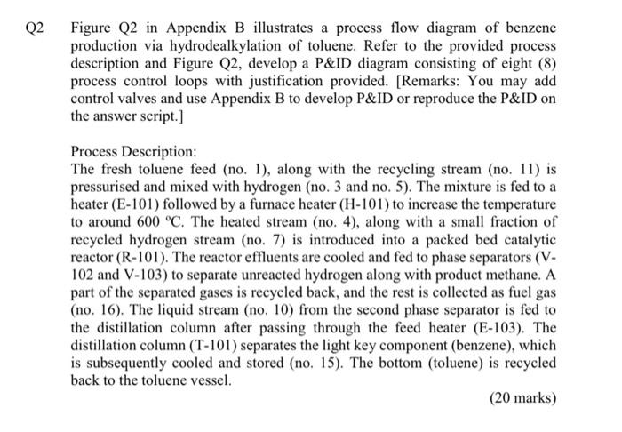
Figure Q2 in Appendix B illustrates a process flow diagram of benzene production via hydrodealkylation of toluene. Refer to the provided process description and Figure Q2, develop a P\&ID diagram consisting of eight (8) process control loops with justification provided. [Remarks: You may add control valves and use Appendix B to develop P\&ID or reproduce the P\&ID on the answer script.] Process Description: The fresh toluene feed (no. 1), along with the recycling stream (no. 11) is pressurised and mixed with hydrogen (no. 3 and no. 5). The mixture is fed to a heater (E101) followed by a furnace heater (H101) to increase the temperature to around 600C. The heated stream (no. 4), along with a small fraction of recycled hydrogen stream (no. 7) is introduced into a packed bed catalytic reactor ( R101). The reactor effluents are cooled and fed to phase separators (V102 and V103 ) to separate unreacted hydrogen along with product methane. A part of the separated gases is recycled back, and the rest is collected as fuel gas (no. 16). The liquid stream (no, 10) from the second phase separator is fed to the distillation column after passing through the feed heater (E-103). The distillation column (T-101) separates the light key component (benzene), which is subsequently cooled and stored (no. 15). The bottom (toluene) is recycled back to the toluene vessel. (20 marks)
Step by Step Solution
There are 3 Steps involved in it

Get step-by-step solutions from verified subject matter experts