

Question: Figure Q.7 shows a shift register counter. Name this counter. Sketch a full cycle timing diagram (4 clock pulses) for output Qo, Q, Q2,
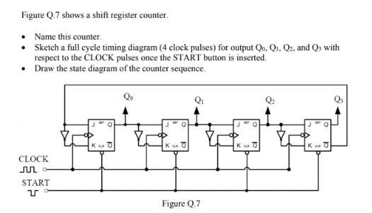
Figure Q.7 shows a shift register counter. Name this counter. Sketch a full cycle timing diagram (4 clock pulses) for output Qo, Q, Q2, and Q3 with respect to the CLOCK pulses once the START button is inserted. Draw the state diagram of the counter sequence. CLOCK JUL START Kud Qo Q KO Figure Q.7 K p .. K SA
Step by Step Solution
There are 3 Steps involved in it
1 Expert Approved Answer
Step: 1 Unlock

Ans 1 a Johnson counter A Johnson counter is a modif... View full answer
Question Has Been Solved by an Expert!
Get step-by-step solutions from verified subject matter experts
Step: 2 Unlock
Step: 3 Unlock