

Figure Qu. 1 below shows a simple Single Line Diagram (SLD) for a power system where...
Fantastic news! We've Found the answer you've been seeking!
Question:
Transcribed Image Text:
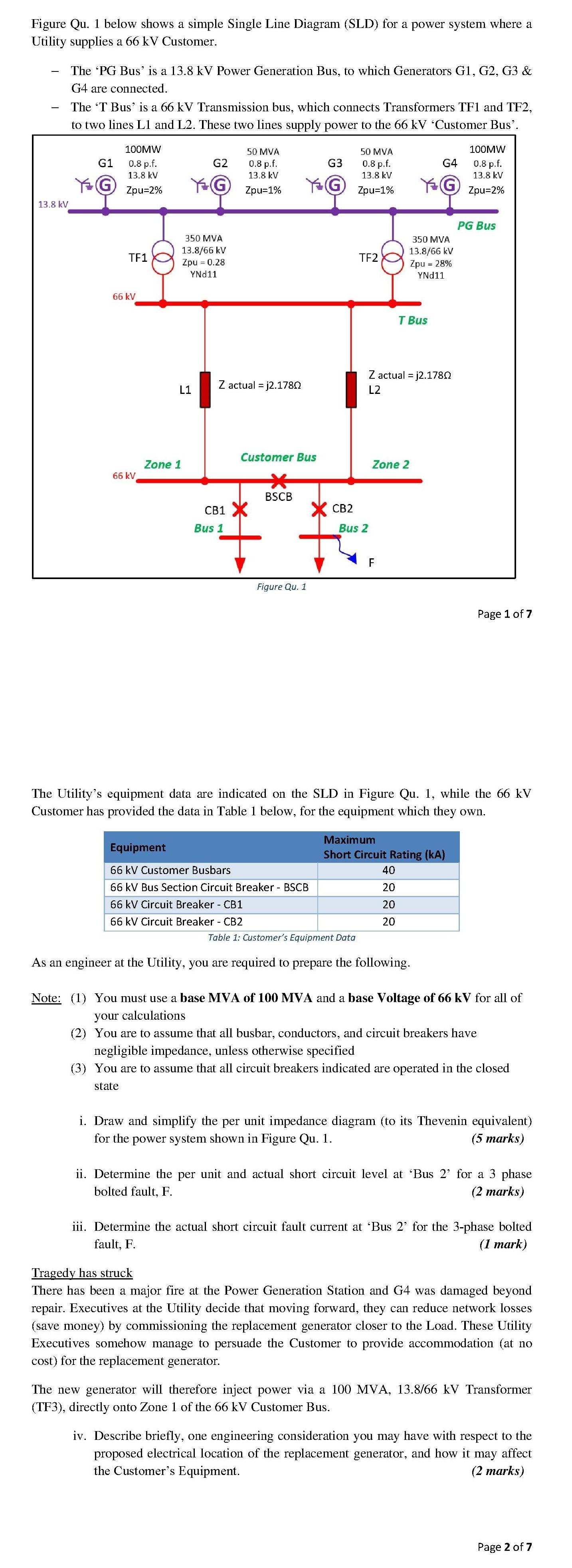
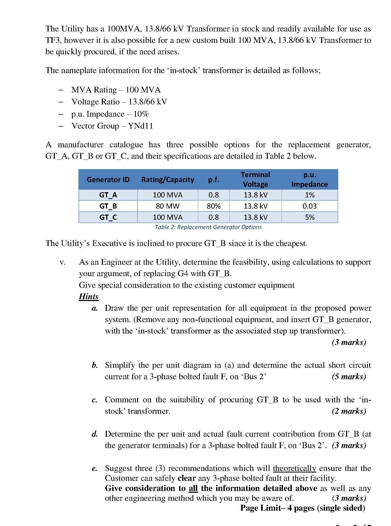
Figure Qu. 1 below shows a simple Single Line Diagram (SLD) for a power system where a Utility supplies a 66 kV Customer. - 13.8 kV The 'PG Bus' is a 13.8 kV Power Generation Bus, to which Generators G1, G2, G3 & G4 are connected. The 'T Bus' is a 66 kV Transmission bus, which connects Transformers TF1 and TF2, to two lines L1 and L2. These two lines supply power to the 66 kV 'Customer Bus'. G1 YG 100MW 0.8 p.f. 13.8 kV Zpu=2% TF1 66 kV 66 kV L1 Zone 1 G2 G 350 MVA 13.8/66 kV Zpu = 0.28 YND11 50 MVA 0.8 p.f. 13.8 kV Zpu=1% Z actual =j2.1780 Bus 1 Customer Bus * BSCB CB1 X Figure Qu. 1 G3 G Equipment 66 kV Customer Busbars 66 kV Bus Section Circuit Breaker - BSCB 66 kV Circuit Breaker - CB1 66 kV Circuit Breaker - CB2 CB2 50 MVA 0.8 p.f. 13.8 kV Zpu=1% TF2 Bus 2 Z actual =j2.1780 L2 F 350 MVA 13.8/66 kV Zpu = 28% YND11 Zone 2 G4 YG T Bus 40 20 20 20 Maximum Short Circuit Rating (KA) The Utility's equipment data are indicated on the SLD in Figure Qu. 1, while the 66 kV Customer has provided the data in Table 1 below, for the equipment which they own. Table 1: Customer's Equipment Data As an engineer at the Utility, you are required to prepare the following. 100MW 0.8 p.f. 13.8 kV Zpu=2% PG Bus Page 1 of 7 Note: (1) You must use a base MVA of 100 MVA and a base Voltage of 66 kV for all of your calculations (2) You are to assume that all busbar, conductors, and circuit breakers have negligible impedance, unless otherwise specified (3) You are to assume that all circuit breakers indicated are operated in the closed state i. Draw and simplify the per unit impedance diagram (to its Thevenin equivalent) for the power system shown in Figure Qu. 1. (5 marks) ii. Determine the per unit and actual short circuit level at 'Bus 2' for a 3 phase bolted fault, F. (2 marks) iii. Determine the actual short circuit fault current at 'Bus 2' for the 3-phase bolted fault, F. (1 mark) Tragedy has struck There has been a major fire at the Power Generation Station and G4 was damaged beyond repair. Executives at the Utility decide that moving forward, they can reduce network losses (save money) by commissioning the replacement generator closer to the Load. These Utility Executives somehow manage to persuade the Customer to provide accommodation (at no cost) for the replacement generator. The new generator will therefore inject power via a 100 MVA, 13.8/66 kV Transformer (TF3), directly onto Zone 1 of the 66 kV Customer Bus. iv. Describe briefly, one engineering consideration you may have with respect to the proposed electrical location of the replacement generator, and how it may affect the Customer's Equipment. (2 marks) Page 2 of 7 The Utility has a 100MVA, 13.8/66 kV Transformer in stock and readily available for use as TF3, however it is also possible for a new custom built 100 MVA, 13.8/66 kV Transformer to be quickly procured, if the need arises. The nameplate information for the 'in-stock' transformer is detailed as follows; - MVA Rating - 100 MVA Voltage Ratio - 13.8/66 kV p.u. Impedance - 10% Vector Group - YNd11 A manufacturer catalogue has three possible options for the replacement generator, GT_A, GT_B or GT_C, and their specifications are detailed in Table 2 below. Terminal Voltage 100 MVA 13.8 kV 80 MW 13.8 kV 100 MVA 13.8 kV Table 2: Replacement Generator Options The Utility's Executive is inclined to procure GT_B since it is the cheapest. V. Generator ID Rating/Capacity GT_A GT_B GT_C p.f. 0.8 80% 0.8 p.u. Impedance 1% 0.03 5% As an Engineer at the Utility, determine the feasibility, using calculations to support your argument, of replacing G4 with GT_B. Give special consideration to the existing customer equipment Hints a. Draw the per unit representation for all equipment in the proposed power system. (Remove any non-functional equipment, and insert GT_B generator, with the 'in-stock' transformer as the associated step up transformer). (3 marks) C. b. Simplify the per unit diagram in (a) and determine the actual short circuit current for a 3-phase bolted fault F, on 'Bus 2' (5 marks) Comment on the suitability of procuring GT_B to be used with the 'in- stock' transformer. (2 marks) d. Determine the per unit and actual fault current contribution from GT_B (at the generator terminals) for a 3-phase bolted fault F, on 'Bus 2'. (3 marks) e. Suggest three (3) recommendations which will theoretically ensure that the Customer can safely clear any 3-phase bolted fault at their facility. Give consideration to all the information detailed above as well as any other engineering method which you may be aware of. (3 marks) Page Limit- 4 pages (single sided) Figure Qu. 1 below shows a simple Single Line Diagram (SLD) for a power system where a Utility supplies a 66 kV Customer. - 13.8 kV The 'PG Bus' is a 13.8 kV Power Generation Bus, to which Generators G1, G2, G3 & G4 are connected. The 'T Bus' is a 66 kV Transmission bus, which connects Transformers TF1 and TF2, to two lines L1 and L2. These two lines supply power to the 66 kV 'Customer Bus'. G1 YG 100MW 0.8 p.f. 13.8 kV Zpu=2% TF1 66 kV 66 kV L1 Zone 1 G2 G 350 MVA 13.8/66 kV Zpu = 0.28 YND11 50 MVA 0.8 p.f. 13.8 kV Zpu=1% Z actual =j2.1780 Bus 1 Customer Bus * BSCB CB1 X Figure Qu. 1 G3 G Equipment 66 kV Customer Busbars 66 kV Bus Section Circuit Breaker - BSCB 66 kV Circuit Breaker - CB1 66 kV Circuit Breaker - CB2 CB2 50 MVA 0.8 p.f. 13.8 kV Zpu=1% TF2 Bus 2 Z actual =j2.1780 L2 F 350 MVA 13.8/66 kV Zpu = 28% YND11 Zone 2 G4 YG T Bus 40 20 20 20 Maximum Short Circuit Rating (KA) The Utility's equipment data are indicated on the SLD in Figure Qu. 1, while the 66 kV Customer has provided the data in Table 1 below, for the equipment which they own. Table 1: Customer's Equipment Data As an engineer at the Utility, you are required to prepare the following. 100MW 0.8 p.f. 13.8 kV Zpu=2% PG Bus Page 1 of 7 Note: (1) You must use a base MVA of 100 MVA and a base Voltage of 66 kV for all of your calculations (2) You are to assume that all busbar, conductors, and circuit breakers have negligible impedance, unless otherwise specified (3) You are to assume that all circuit breakers indicated are operated in the closed state i. Draw and simplify the per unit impedance diagram (to its Thevenin equivalent) for the power system shown in Figure Qu. 1. (5 marks) ii. Determine the per unit and actual short circuit level at 'Bus 2' for a 3 phase bolted fault, F. (2 marks) iii. Determine the actual short circuit fault current at 'Bus 2' for the 3-phase bolted fault, F. (1 mark) Tragedy has struck There has been a major fire at the Power Generation Station and G4 was damaged beyond repair. Executives at the Utility decide that moving forward, they can reduce network losses (save money) by commissioning the replacement generator closer to the Load. These Utility Executives somehow manage to persuade the Customer to provide accommodation (at no cost) for the replacement generator. The new generator will therefore inject power via a 100 MVA, 13.8/66 kV Transformer (TF3), directly onto Zone 1 of the 66 kV Customer Bus. iv. Describe briefly, one engineering consideration you may have with respect to the proposed electrical location of the replacement generator, and how it may affect the Customer's Equipment. (2 marks) Page 2 of 7 The Utility has a 100MVA, 13.8/66 kV Transformer in stock and readily available for use as TF3, however it is also possible for a new custom built 100 MVA, 13.8/66 kV Transformer to be quickly procured, if the need arises. The nameplate information for the 'in-stock' transformer is detailed as follows; - MVA Rating - 100 MVA Voltage Ratio - 13.8/66 kV p.u. Impedance - 10% Vector Group - YNd11 A manufacturer catalogue has three possible options for the replacement generator, GT_A, GT_B or GT_C, and their specifications are detailed in Table 2 below. Terminal Voltage 100 MVA 13.8 kV 80 MW 13.8 kV 100 MVA 13.8 kV Table 2: Replacement Generator Options The Utility's Executive is inclined to procure GT_B since it is the cheapest. V. Generator ID Rating/Capacity GT_A GT_B GT_C p.f. 0.8 80% 0.8 p.u. Impedance 1% 0.03 5% As an Engineer at the Utility, determine the feasibility, using calculations to support your argument, of replacing G4 with GT_B. Give special consideration to the existing customer equipment Hints a. Draw the per unit representation for all equipment in the proposed power system. (Remove any non-functional equipment, and insert GT_B generator, with the 'in-stock' transformer as the associated step up transformer). (3 marks) C. b. Simplify the per unit diagram in (a) and determine the actual short circuit current for a 3-phase bolted fault F, on 'Bus 2' (5 marks) Comment on the suitability of procuring GT_B to be used with the 'in- stock' transformer. (2 marks) d. Determine the per unit and actual fault current contribution from GT_B (at the generator terminals) for a 3-phase bolted fault F, on 'Bus 2'. (3 marks) e. Suggest three (3) recommendations which will theoretically ensure that the Customer can safely clear any 3-phase bolted fault at their facility. Give consideration to all the information detailed above as well as any other engineering method which you may be aware of. (3 marks) Page Limit- 4 pages (single sided)
Expert Answer:

Related Book For 
Posted Date:
Students also viewed these electrical engineering questions
-
A company has an optimal capital structure as follows: Total Assets $600,000 Debt $300,000 Preferred Stock $100,000 Common Equity $200,000 What would be the minimum expected return from a new capital...
-
1. Consider the utility function U(X)=X1.X2. a. Check whether the above function is strictly quasi concave. b. Solve the U-Max problem for the consumer and find X1 and X2 in terms of P1, P2 and M....
-
The following additional information is available for the Dr. Ivan and Irene Incisor family from Chapters 1-5. Ivan's grandfather died and left a portfolio of municipal bonds. In 2012, they pay Ivan...
-
QUESTION THREE The following is an extract of a trial balance of Ruslan-Ford Partners as at 28 February 2023 Capital: Ruslan Capital: Ford Current account: Ruslan 01/03/2022 Current account: Ford...
-
The immediate roof behind a long wall face often considered to be a cantilever beam as shown in section in the sketch. Beginning with a safety factor design criterion, derive an expression for the...
-
Give two reasons shareholders might be indifferent between owning the stock of a firm with volatile cash flows and that of a firm with table cash flows?
-
(a) As the electric motor shown schematically in Figure P28.30 operates, which of the arrows shown could represent the magnetic dipole moment at various instants? (b) If there are any arrows that are...
-
Prepare a physical DFD based on the output from Short Problem.
-
6. The number of (staircase) paths in the xy-plane from (0, 0) to (7, 5) where each such path is made up of individual steps going one unit upward (U) or one unit to the right (R). (a) 12C5 (b) 12!...
-
Consider the following relation: CAR_SALE(Car#, Date_sold, Salesperson#, Commission%, Discount_amt) Assume that a car may be sold by multiple salespeople, and hence {Car#, Salesperson#} is the...
-
Assume that you are a mortgage broker employee wanting to sharpen your Personal Professional Development Plan. You are to call or meet with the relevant personnel in your workplace to seek feedback...
-
Dissolution of ammonium nitrate in water Fill a 100 mL beaker half-full with water. Place your hand on the outside of the beaker to gauge the temperature. Add a large scoop of ammonium nitrate to the...
-
Write a program in Java, ( 1 ) "fibonacci" - Takes as argument a single non - zero, positive integer and prints the fibonacci series up to the highest fibonacci number that is smaller or equal to the...
-
Your company, Deep Blue, is based in Navi, a country on Pandora, a mythical world with zero transportation costs, no trade barriers, and vastly different factor endowments amongst countries. Your...
-
A metal sphere of radius a contains a charge +Q and is surrounded by an uncharged, concentric, metallic shell of inner radius b and outer radius c, as shown above. Express all algebraic answers in...
-
Assume that the perfectly competitive firm and the imperfectly competitive firm have the same costs as shown in the table below. Fill in the table and answer the following questions. Marginal...
-
2. Suppose that JP Morgan Chase; the Bank of England, and the Bank of China agree that they will not compete for investment services and that JPMorgan Chase is given an exclusive right to North and...
-
For what reason might an exporter use standard international trade documentation (letter of credit, draft, order bill of lading) on an intrafirm export to its parent or sister subsidiary?
-
Solve for x(t) in the system shown in Figure P4.5 if f (t) is a unit step. x(t) M = 2 kg Ks K, = 6 N/m fy = 2 N-s/m f(1) = u(1)N 000 M f(t) FIGURE P4.5
-
Find the percent overshoot, settling time, rise time, and peak time for 14.65 T(s) (s2 + 0.842s + 2.93)(s + 5)
-
Using the Routh-Hurwitz criterion, find the value of K that will yield oscillations for the unity feedback system of Figure P6.3 with K G(s) = (s + 77)(s+ 27)(s + 38) R(s) + E(s) C(s) G(s) FIGURE P6.3
-
Eugene Fama and Robert Shiller recently won the Nobel Prize in economics. Go to http://nobelprize.org/nobel_prizes/economics/ and locate the press release on Eugene Fama and Robert Shiller. What was...
-
Visit the Bloomberg Markets website at www.bloomberg.com/markets/stocks. Their interactive graph allows you to see cumulative returns for individual stocks as well as market indices. Over the last...
-
Compute the price of a share of stock that pays a \($5\) per year dividend and that you expect to be able to sell in one year for \($40\), assuming you require a 5% return.

Study smarter with the SolutionInn App