

Question: For the continuous beam shown in ( Figure 1 ) , assume A is fixed and B and C are rollers. Let w = 0
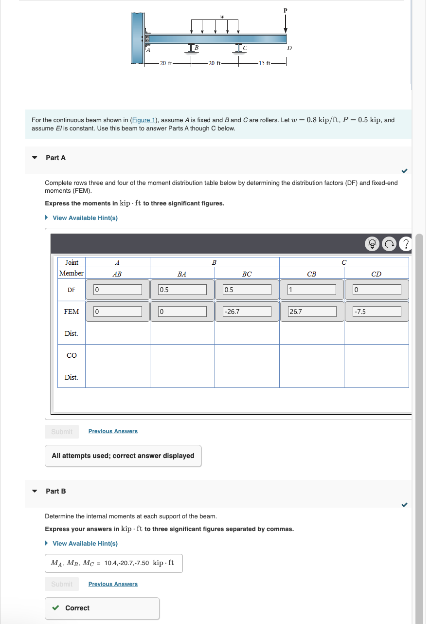
For the continuous beam shown in Figure assume is fixed and and are rollers. Let kip, and assume is constant. Use this beam to answer Parts A though C below. Part C
Draw the moment diagram for the entire beam.
Begin by placing lines of discontinuity.
Note Make sure you place only one vertical line at places that require a vertical line. If you inadvertently place vertical lines at the same place, it will appear
correct visually because the lines overlap, but the system will mark it wrong.
View Available Hints
No elements selected
Press SPACE to restore all settings to the default. Press TAB to go to the next option. Press ALTY to get to the elements on the
canvas. Press
to modify the attributes. Press ALTQ to quit the application.
Part A
Complete rows three and four of the moment distribution table below by determining the distribution factors DF and fixedend moments FEM
Express the moments in kip to three significant figures.
View Available Hints
tableJointABCMemberABBABCCBCDDFFEMDistCODist
Previous Answers
All attempts used; correct answer displayed
Part B
Determine the internal moments at each support of the beam.
Express your answers in kip to three significant figures separated by commas.
View Available Hints
Previous A
JUST NEED PART C
Step by Step Solution
There are 3 Steps involved in it
1 Expert Approved Answer
Step: 1 Unlock

Question Has Been Solved by an Expert!
Get step-by-step solutions from verified subject matter experts
Step: 2 Unlock
Step: 3 Unlock