

Question: For the truss shown below, the support at A is a roller, and C is a pin. E = 3 0 1 0 6 l
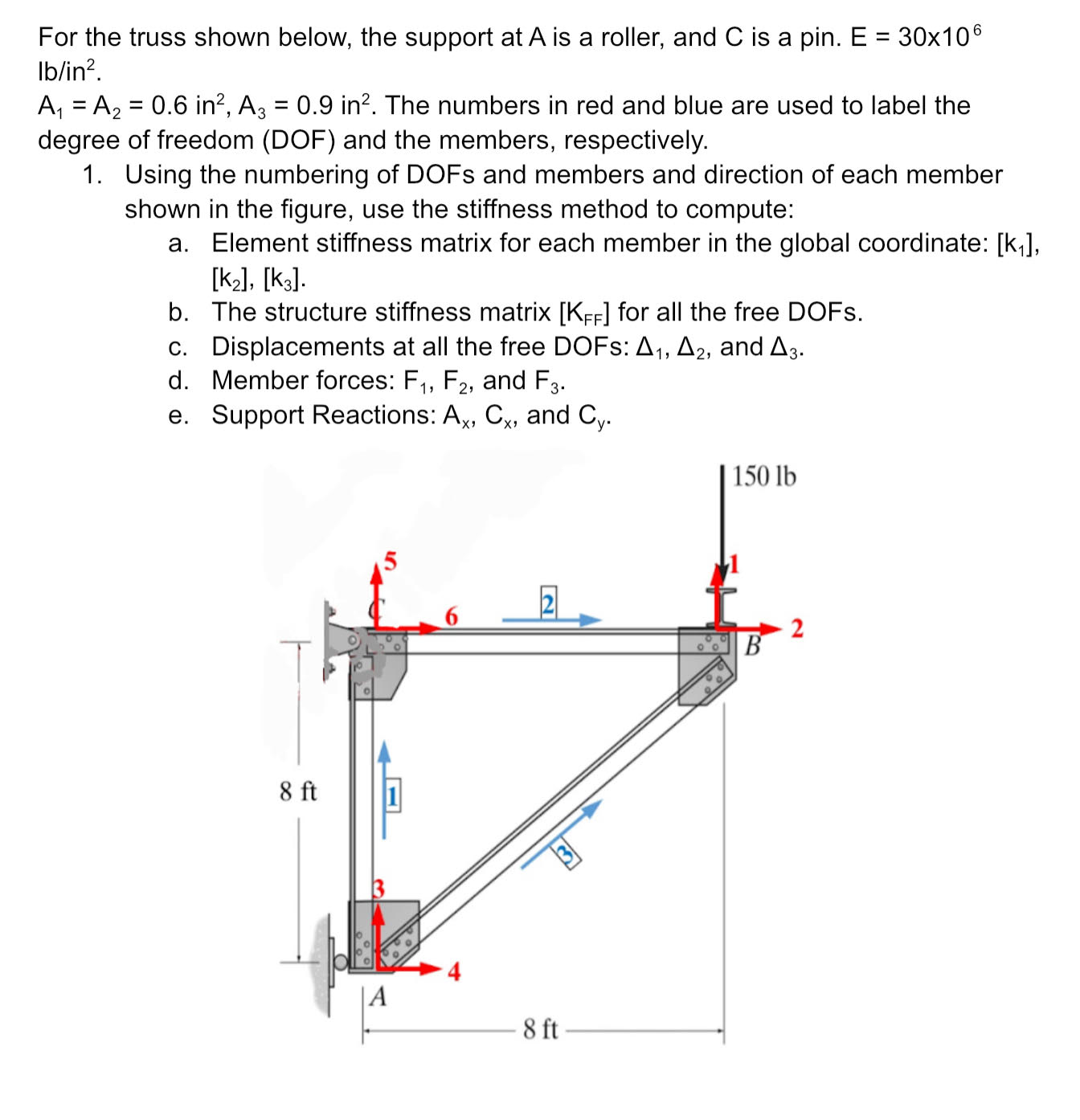
For the truss shown below, the support at is a roller, and is a pin.
The numbers in red and blue are used to label the degree of freedom DOF and the members, respectively.
Using the numbering of DOFs and members and direction of each member shown in the figure, use the stiffness method to compute:
a Element stiffness matrix for each member in the global coordinate:
b The structure stiffness matrix for all the free DOFs.
c Displacements at all the free DOFs: and
d Member forces: and
e Support Reactions: and
Step by Step Solution
There are 3 Steps involved in it
1 Expert Approved Answer
Step: 1 Unlock

Question Has Been Solved by an Expert!
Get step-by-step solutions from verified subject matter experts
Step: 2 Unlock
Step: 3 Unlock