

Question: Given the FPGA in Figure 3 below, implement logic for the next state n 0 = F ( s 1 , s 0 , a
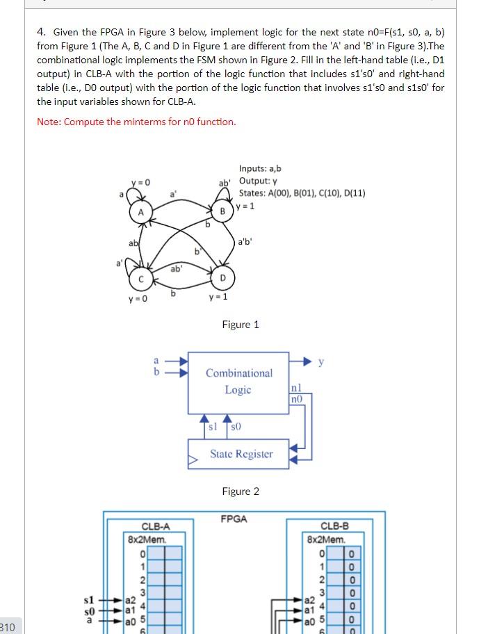
Given the FPGA in Figure below, implement logic for the next state nFs s a b from Figure The A B C and D in Figure are different from the A and B in Figure The combinational logic implements the FSM shown in Figure Fill in the lefthand table ie D output in CLBA with the portion of the logic function that includes ss and righthand table ie D output with the portion of the logic function that involves ss and ss for the input variables shown for CLBA
Note: Compute the minterms for n function.
PLEASE EXPLAIN AND SOLVE BOTH TABELS.
Step by Step Solution
There are 3 Steps involved in it
1 Expert Approved Answer
Step: 1 Unlock

Question Has Been Solved by an Expert!
Get step-by-step solutions from verified subject matter experts
Step: 2 Unlock
Step: 3 Unlock