

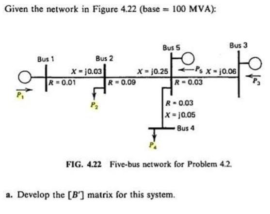
Question: Given the network in Figure 4.22 (base = 100 MVA): Bus 1 G Bus 2 R=0.09 X-10.03 R = 0.01 Bus 5 X =
![Solve for the [B] - matrix. e02 03 04 os PP2 [B] P. PA c. Calculate the phase angles for the set of power injections. Pi](https://dsd5zvtm8ll6.cloudfront.net/si.experts.images/questions/2022/08/630dafa28a2f8_1661841313894.jpg)
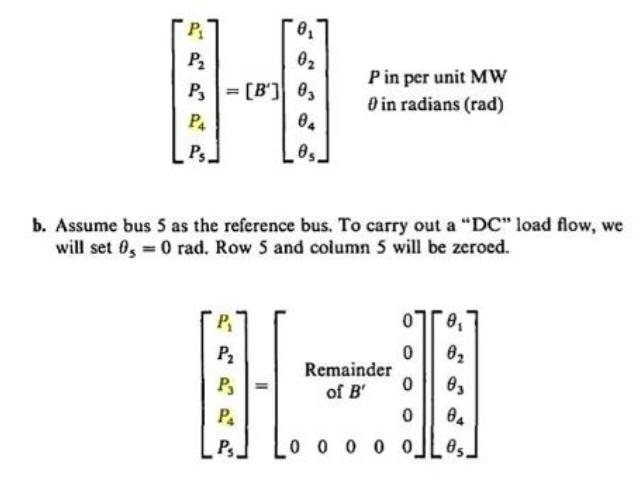
Given the network in Figure 4.22 (base = 100 MVA): Bus 1 G Bus 2 R=0.09 X-10.03 R = 0.01 Bus 5 X = 10.25 R = 0.03 Ps X = 10.06 R=0.03 X = 10.05 Bus 4 Bus 3 a. Develop the [B'] matrix for this system. FIG. 4.22 Five-bus network for Problem 4.2. P 0 P 0 P = [B'] 0, 04 Ps. 05. P in per unit MW 0 in radians (rad) b. Assume bus 5 as the reference bus. To carry out a "DC" load flow, we will set 0,= 0 rad. Row 5 and column 5 will be zeroed. P P P P Ps. 0 0 0 0 0 0 0 0 Remainder of B' 0 0 03 04 Solve for the [B'] matrix. 0 0 03 04 05. = P P [B'] P PA c. Calculate the phase angles for the set of power injections. P = 100 MW generation P= 120 MW load P3150 MW generation P200 MW load d. Calculate P, according to the "DC" load flow. e. Calculate all power flows on the system using the phase angles found in part c.
Step by Step Solution
3.42 Rating (149 Votes )
There are 3 Steps involved in it
We have tv ferest form for the given system Y Y 421 YIL 412 Y Y2 Y3 422 421 YA 951 ... View full answer

Get step-by-step solutions from verified subject matter experts