

Question: Spin Direction Detector Consider a system which consists of a spinning circular disk and stationary probes A (at 12 o'clock on the disk frame)
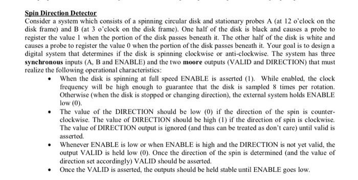

Spin Direction Detector Consider a system which consists of a spinning circular disk and stationary probes A (at 12 o'clock on the disk frame) and B (at 3 o'clock on the disk frame). One half of the disk is black and causes a probe to register the value 1 when the portion of the disk passes beneath it. The other half of the disk is white and causes a probe to register the value 0 when the portion of the disk passes beneath it. Your goal is to design a digital system that determines if the disk is spinning clockwise or anti-clockwise. The system has three synchronous inputs (A, B and ENABLE) and the two moore outputs (VALID and DIRECTION) that must realize the following operational characteristics: When the disk is spinning at full speed ENABLE is asserted (1). While enabled, the clock frequency will be high enough to guarantee that the disk is sampled 8 times per rotation. Otherwise (when the disk is stopped or changing direction), the external system holds ENABLE low (0). The value of the DIRECTION should be low (0) if the direction of the spin is counter- clockwise. The value of DIRECTION should be high (1) if the direction of spin is clockwise. The value of DIRECTION output is ignored (and thus can be treated as don't care) until valid is asserted. Whenever ENABLE is low or when ENABLE is high and the DIRECTION is not yet valid, the output VALID is held low (0). Once the direction of the spin is determined (and the value of direction set accordingly) VALID should be asserted. Once the VALID is asserted, the outputs should be held stable until ENABLE goes low. [1 points] Implement this design using the lab simulator. Draw or print a schematic for the circuit using D-type flip-flops with the SSI and MSI parts of your choice for the next state and output logic. Provide complete documentation for this schematic.
Step by Step Solution
There are 3 Steps involved in it
To design this circuit youll break the problem into the following steps Step 1 Understand InputOutput Inputs A B ENABLE Outputs VALID DIRECTION Probes ... View full answer

Get step-by-step solutions from verified subject matter experts