

Question: Here is the Code Template we were provided to use. (Only got to put code where it says Replace this comment block. Everything else is
Here is the Code Template we were provided to use. (Only got to put code where it says "Replace this comment block". Everything else is given pretty much)
`timescale 1ns / 1ps
//////////////////////////////////////////////////////////////////////////////////
// Company:
// Engineer:
//
// Create Date: 10/10/2018 05:09:40 PM
// Design Name:
// Module Name: BCD2Binary
// Project Name:
// Target Devices:
// Tool Versions:
// Description:
//
// Dependencies:
//
// Revision:
// Revision 0.01 - File Created
// Additional Comments:
//
//////////////////////////////////////////////////////////////////////////////////
// Top Module
module bcd2bin
(
input [3:0]bcd2,bcd1,bcd0,
input clk,start,
output [9:0]bin
);
// "localparam" is a constant label in Verilog, that way
// we can give a name to a value. For example, we
// let the constant label "idle" equal 2'b00
// This makes the Verilog code easier to read/understand,
// in this case, idle will serve as one of our 3 states.
localparam [1:0]
idle = 2'b00,
conversion = 2'b01,
done = 2'b10;
// Creating the necessary registers, since we are modeling
// an FSMD. Refer to the comments at the always blocks for
// more info on these registers.
reg [3:0]counter,counterNext,bcd2Temp,bcd1Temp,bcd0Temp;
reg [11:0]bcdReg,bcdRegNext;
reg [9:0]binReg,binRegNext;
reg [1:0]state,nextState;
// Initial block used in main code only for
// simulation purposes only to "set-up" defined
// values for our internal registers.
initial
begin
counter = 'd0;
counterNext = 'd0;
bcdReg = 'd0;
bcdRegNext = 'd0;
binReg = 'd0;
binRegNext = 'd0;
state = 'd0;
nextState = 'd0;
end
// The main difference between the current and next
// registers, is that the current registers are the
// synchronized values while the next registers are
// the next-unsynchronized values to be synchronized
// on next posedge of clk.
//-------------------------------------------------------
// The purpose of this
// always block is to keep the unit synchronous and also
// provide the current state and current register data.
always@(posedge clk)
begin
state
bcdReg
binReg
counter
end
// This always block executes not on the posedge of
// clock (like the last always block) but executes
// on any change in any of the right-hand elements
// within this block; this is done by using "*".
// -----------------------------------------------
// The purpose of this always bock is to get the
// next state logic
always@*
begin
nextState = state;
bcdRegNext = bcdReg;
binRegNext = binReg;
counterNext = counter;
// A case-statement for our 3 states
case(state)
// Idle state, waits for start signal
idle:
begin
if(start)
begin
bcdRegNext = {bcd2,bcd1,bcd0}; // Group the inputs
counterNext = 4'b1010; // Get counter ready
nextState = conversion; // Get next state
end
end
// This state does the conversion, this 3-BCD digit
// to binary takes 10 cycles/shifts to complete
// (since the largest answer will be 999 which is
// 1111100111 in binary)
conversion:
begin
bcdRegNext = bcdRegNext
binRegNext = bcdRegNext;
// {
// 1. Replace this comment block with the shift
// logic. How can we, in Verilog, shift the
// least-sig bit of bcdRegNext to the most-sig bit
// of binRegNext? There's different ways of doing
// this. Hint: Remember bit selection (i.e. x[1]),
// concatenation (i.e. {x[1],somethingElse[3:1]},
// and also the shift operator (i.e. x = x >> 1).
// The shift operator is straightforward if you go
// that route, but you can also use concatenation of
// certain bits in a reg to "emulate" a shift.
// One solution to this takes just 2 lines to do this
// shifting between these two different registers just
// an FYI.
// }
if(bcdRegNext[11:8] >= 4'b1000)
begin
// {
// 2. Replace this comment block with the
// logic that subtracts 3 from just the 3rd
// nibble from bcdRegNext and restore
// that new nibble to the same position
// in the bcdRegNext without changing any other
// bits in that register. Hint: I defined the
// "bcd2Temp" registers for a reason, perhaps
// you can use them as temporary storage? Also,
// don't forget that Verilog lets you select certain bits
// from a register array using []'s.
// (i.e. an example is shown in this if-statement block)
// }
end
if(bcdRegNext[7:4] >= 4'b1000)
begin
// {
// 2. Replace this comment block with the
// logic that subtracts 3 from just the 2nd
// nibble from bcdRegNext and restore
// that new nibble to the same position
// in the bcdRegNext without changing any other
// bits in that register. Hint: I defined the
// "bcd1Temp" registers for a reason, perhaps
// you can use them as temporary storage? Also,
// don't forget that Verilog lets you select certain bits
// from a register array using []'s.
// (i.e. an example is shown in this if-statement block)
// }
end
if(bcdRegNext[3:0] >= 4'b1000)
begin
// {
// 2. Replace this comment block with the
// logic that subtracts 3 from just the 1st
// nibble from bcdRegNext and restore
// that new nibble to the same position
// in the bcdRegNext without changing any other
// bits in that register. Hint: I defined the
// "bcd0Temp" registers for a reason, perhaps
// you can use them as temporary storage? Also,
// don't forget that Verilog lets you select certain bits
// from a register array using []'s.
// (i.e. an example is shown in this if-statement block)
// }
end
counterNext = counterNext - 1; // Decrement counterNext
// When last conversion shift is encountered,
// go to the next state
if(counterNext == 0)
begin
nextState = done;
end
end
// Finished state, go back to idle
done:
begin
nextState = idle;
end
endcase
end
// This links the output "bin" to the value of the binReg register
assign bin = binReg;
endmodule
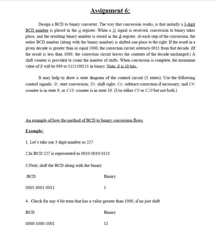
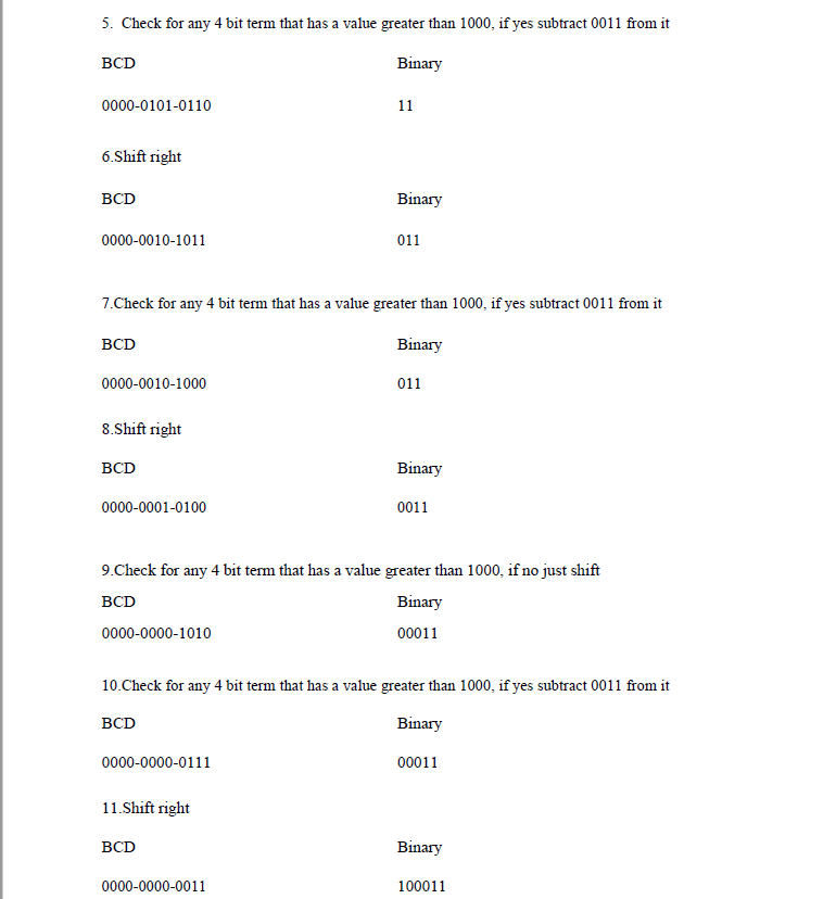
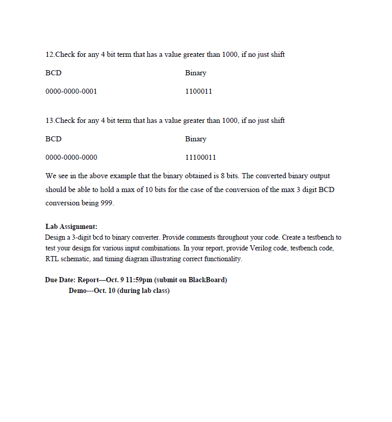
Assignment 6: Design a BCD to binary converter. The way that conversion works, is that initially a 3-digit BCD number is placed in the A register. When a St signal is received, conversion to binary takes place, and the resulting binary number is stored in the B register. At each step of the conversion, the entire BCD number (along with the binary number) is shifted one place to the right. If the result in a given decade is greater than or equal 1000, the correction circuit subtracts 0011 from that decade. (If the result is less than 1000, the correction circuit leaves the contents of the decade unchanged.) A shift counter is provided to count the number of shifts. When conversion is complete, the maximum It may help to draw a state diagram of the control circuit (3 states). Use the following control signals: St: start conversion; Sh: shift right; Co: subtract correction if necessary; and C9: counter is in state 9, or C10: counter is in state 10. (Use either C9 or C10 but not both.) OW Erample: 1. Let's take our 3 digit number as 227 2.In BCD 227 is represented as 0010-0010-0111 3 Next, shift the BCD along with the binary BCD Binary 0001-0001-0011 4. Check for any 4 bit term that has a value greater than 1000, if no just shift BCD Binary 0000-1000-1001 Assignment 6: Design a BCD to binary converter. The way that conversion works, is that initially a 3-digit BCD number is placed in the A register. When a St signal is received, conversion to binary takes place, and the resulting binary number is stored in the B register. At each step of the conversion, the entire BCD number (along with the binary number) is shifted one place to the right. If the result in a given decade is greater than or equal 1000, the correction circuit subtracts 0011 from that decade. (If the result is less than 1000, the correction circuit leaves the contents of the decade unchanged.) A shift counter is provided to count the number of shifts. When conversion is complete, the maximum It may help to draw a state diagram of the control circuit (3 states). Use the following control signals: St: start conversion; Sh: shift right; Co: subtract correction if necessary; and C9: counter is in state 9, or C10: counter is in state 10. (Use either C9 or C10 but not both.) OW Erample: 1. Let's take our 3 digit number as 227 2.In BCD 227 is represented as 0010-0010-0111 3 Next, shift the BCD along with the binary BCD Binary 0001-0001-0011 4. Check for any 4 bit term that has a value greater than 1000, if no just shift BCD Binary 0000-1000-1001
Step by Step Solution
There are 3 Steps involved in it

Get step-by-step solutions from verified subject matter experts