

Question: Homework 1 0 1 . The ASM chart below describes the operation of a synchronous FSM with scalar binary input and output signals denoted with
Homework
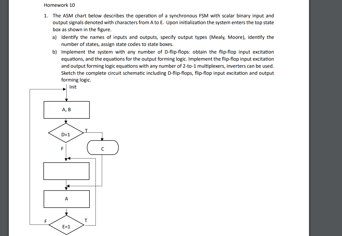
The ASM chart below describes the operation of a synchronous FSM with scalar binary input and output signals denoted with characters from A to E Upon initialization the system enters the top state box as shown in the figure.
a Identify the names of inputs and outputs, specify output types Mealy Moore identify the number of states, assign state codes to state boxes.
b Implement the system with any number of Dflipflops: obtain the flipflop input excitation equations, and the equations for the output forming logic. Implement the flipflop input excitation and output forming logic equations with any number of to multiplexers, inverters can be used. Sketch the complete circuit schematic including Dflipflops, flipflop input excitation and output forming logic.
Step by Step Solution
There are 3 Steps involved in it
1 Expert Approved Answer
Step: 1 Unlock

Question Has Been Solved by an Expert!
Get step-by-step solutions from verified subject matter experts
Step: 2 Unlock
Step: 3 Unlock