

Question: How do I do this 16. Four resistors are connected to a battery as shown in Figure P2816. (a) Determine the potential difference across each
How do I do this
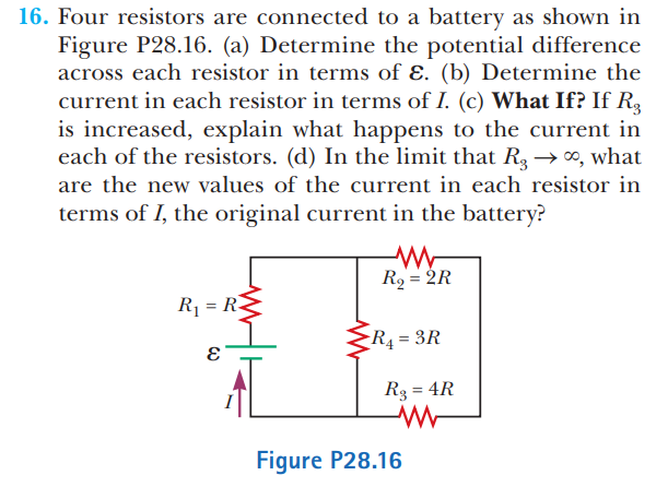
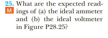
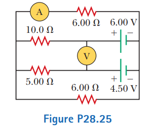
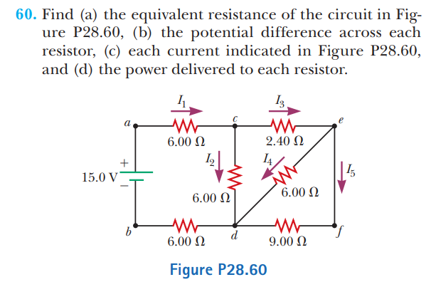
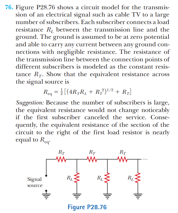
16. Four resistors are connected to a battery as shown in Figure P2816. (a) Determine the potential difference across each resistor in terms of 8. (b) Determine the current in each resistor in terms of I. (c) What If?I If R3 is increased, explain what happens to the current in each of the resistors. (d) In the limit that R3 > 00, what are the new values of the current in each resistor in terms of I, the original current in the battery? Figure P2816 25. What are the expected read- III ings of (a) the ideal ammeter and (b) the ideal voltmeter in Figure P2825? A 6.00 0 6.00 V 10.0 0 + V 5.00 0 + 6.00 0 4.50 V Figure P28.2533. In Figure P2833, find (a) the current in each resistor and (b) the power delivered to each resistor. 24.0v _ + 28.0.0 16.0 (I Figure P2833 60. Find (a) the equivalent resistance of the circuit in Fig- ure P2860, (b) the potential difference across each resistor, (c) each current indicated in Figure P2850, and (d) the power delivered to each resistor. b 5.00 o d 9.00 (1 Figure P28.60 76. Figure P2875 shows a circuit model for the transmis- sion of an electrical signal such as cable TV to a large number of subscribers. Each subscriber connects a load resistance RL between the transmission line and the ground. The ground is assumed to be at zero potential and able to carry any current between any ground con- nections with negligible resistance. The resistance of the transmission line between the connection points of different subscribers is modeled as the constant resis- tance RT. Show that the equivalent resistance across the signal source is 12..l = %[(4RTRL + 33)\" + RT] Suggestion: Because the number of subscribers is large, the equivalent resistance would not change noticeably if the first subscriber canceled the service. Conse- quently, the equivalent resistance of the section of the circuit to the right of the rst load resistor is nearly equal to Rm. Signal SOUFCC - Figure P2B.76
Step by Step Solution
There are 3 Steps involved in it

Get step-by-step solutions from verified subject matter experts