

Question: I am confused about how to do problem 8 bellow, I have my design values IF you need more detail, please look bellow 8. Also

I am confused about how to do problem 8
bellow, I have my design values
IF you need more detail, please look bellow
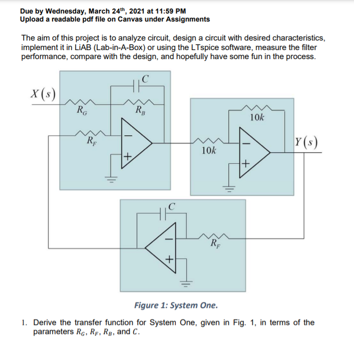
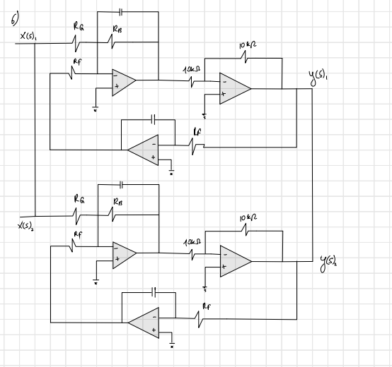
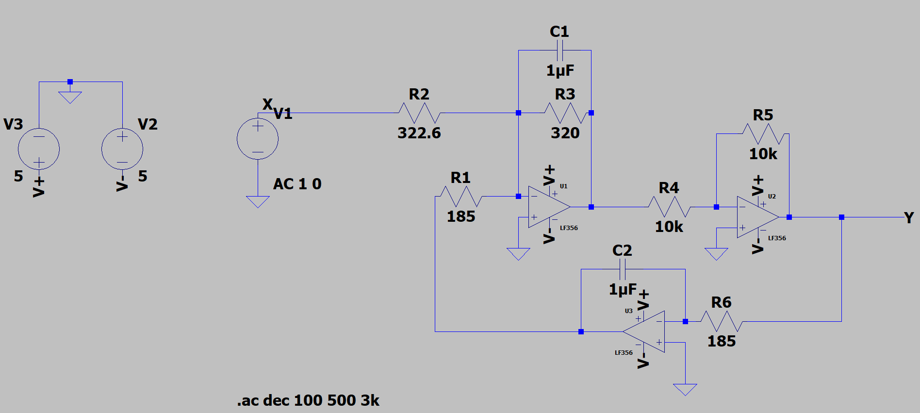
8. Also repeat item 5 for the subtractive parallel combination, i.e. System One minus System Two. HE 0 RA Re 10kR AA RF 440 yes), LE La 2s 102 RF U + 2% C1 1uF R3 R2 Xvi R5 V3 V2 322.6 320 10k 5 +-+A V- 5 AC 1 0 R1 V+ 01 R4 U2 185 Y LF356 10k > LF356 C2 > 1uF. $ R6 U3 185 LF356 $ .ac dec 100 500 3k. Due by Wednesday, March 24th, 2021 at 11:59 PM Upload a readable pdf file on Canvas under Assignments The aim of this project is to analyze circuit, design a circuit with desired characteristics, implement it in LIAB (Lab-in-A-Box) or using the LTspice software, measure the filter performance, compare with the design, and hopefully have some fun in the process. X($) Ro RB 10k RE 10k + + RF + Figure 1: System One. 1. Derive the transfer function for System One, given in Fig. 1, in terms of the parameters RG, Rp, RB, and C. 5. Implement your filter in LIAB and measure its performance in terms of Bode plots. In your report, each plot should contain the measured and the analytical result, for ease of direct comparison. How do the measured and analytically expected results compare? Explain any discrepancies and report any follow up on your hypotheses. 6. In parallel with System One you should put System Two, which is constructed just like System One, but it has different parameters: a max gain of 0 dB and a center frequency equal to the geometric mean of 3 dB edge frequencies 2.0 kHz and 3.0 kHz. 7. Repeat item 5 for the additive parallel combination of System One plus System Two. 8. Also repeat item 5 for the subtractive parallel combination, i.e. System One minus System Two. 8. Also repeat item 5 for the subtractive parallel combination, i.e. System One minus System Two. HE 0 RA Re 10kR AA RF 440 yes), LE La 2s 102 RF U + 2% C1 1uF R3 R2 Xvi R5 V3 V2 322.6 320 10k 5 +-+A V- 5 AC 1 0 R1 V+ 01 R4 U2 185 Y LF356 10k > LF356 C2 > 1uF. $ R6 U3 185 LF356 $ .ac dec 100 500 3k. Due by Wednesday, March 24th, 2021 at 11:59 PM Upload a readable pdf file on Canvas under Assignments The aim of this project is to analyze circuit, design a circuit with desired characteristics, implement it in LIAB (Lab-in-A-Box) or using the LTspice software, measure the filter performance, compare with the design, and hopefully have some fun in the process. X($) Ro RB 10k RE 10k + + RF + Figure 1: System One. 1. Derive the transfer function for System One, given in Fig. 1, in terms of the parameters RG, Rp, RB, and C. 5. Implement your filter in LIAB and measure its performance in terms of Bode plots. In your report, each plot should contain the measured and the analytical result, for ease of direct comparison. How do the measured and analytically expected results compare? Explain any discrepancies and report any follow up on your hypotheses. 6. In parallel with System One you should put System Two, which is constructed just like System One, but it has different parameters: a max gain of 0 dB and a center frequency equal to the geometric mean of 3 dB edge frequencies 2.0 kHz and 3.0 kHz. 7. Repeat item 5 for the additive parallel combination of System One plus System Two. 8. Also repeat item 5 for the subtractive parallel combination, i.e. System One minus System Two
Step by Step Solution
There are 3 Steps involved in it

Get step-by-step solutions from verified subject matter experts