

Question: I have the 4-bit full adder, and please draw a picture of the circuit for step 2(4-bit resettable register) or step 3(a control unit/decoder). If
I have the 4-bit full adder, and please draw a picture of the circuit for step 2(4-bit resettable register) or step 3(a control unit/decoder). If you can't do that, don't answer it. I don't accept the steps of doing it. Please I need it asap!!!!
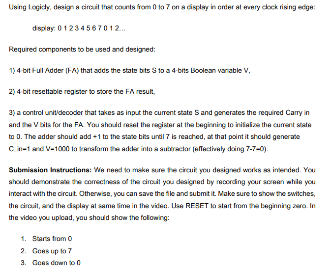
display: 01234567012 Required components to be used and designed: 1) 4-bit Full Adder (FA) that adds the state bits S to a 4-bits Boolean variable V, 2) 4-bit resettable register to store the FA result, 3) a control unit/decoder that takes as input the current state S and generates the required Carry in and the V bits for the FA. You should reset the register at the beginning to initialize the current state to 0 . The adder should add +1 to the state bits until 7 is reached, at that point it should generate C_in=1 and V=1000 to transform the adder into a subtractor (effectively doing 77=0 ). Submission Instructions: We need to make sure the circuit you designed works as intended. You should demonstrate the correctness of the circuit you designed by recording your screen while you interact with the circuit. Otherwise, you can save the file and submit it. Make sure to show the switches, the circuit, and the display at same time in the video. Use RESET to start from the beginning zero. In the video you upload, you should show the following: 1. Starts from 0
Step by Step Solution
There are 3 Steps involved in it

Get step-by-step solutions from verified subject matter experts