

Question: I have this final project for my computer programming class where I make a calculator on Altera. Someone said I have to make a state
I have this final project for my computer programming class where I make a calculator on Altera. Someone said I have to make a state diagram for it and then program it using muxs and gates from the expressions I get fromt those. Please tell me where to start because I have no idea where to start this project.
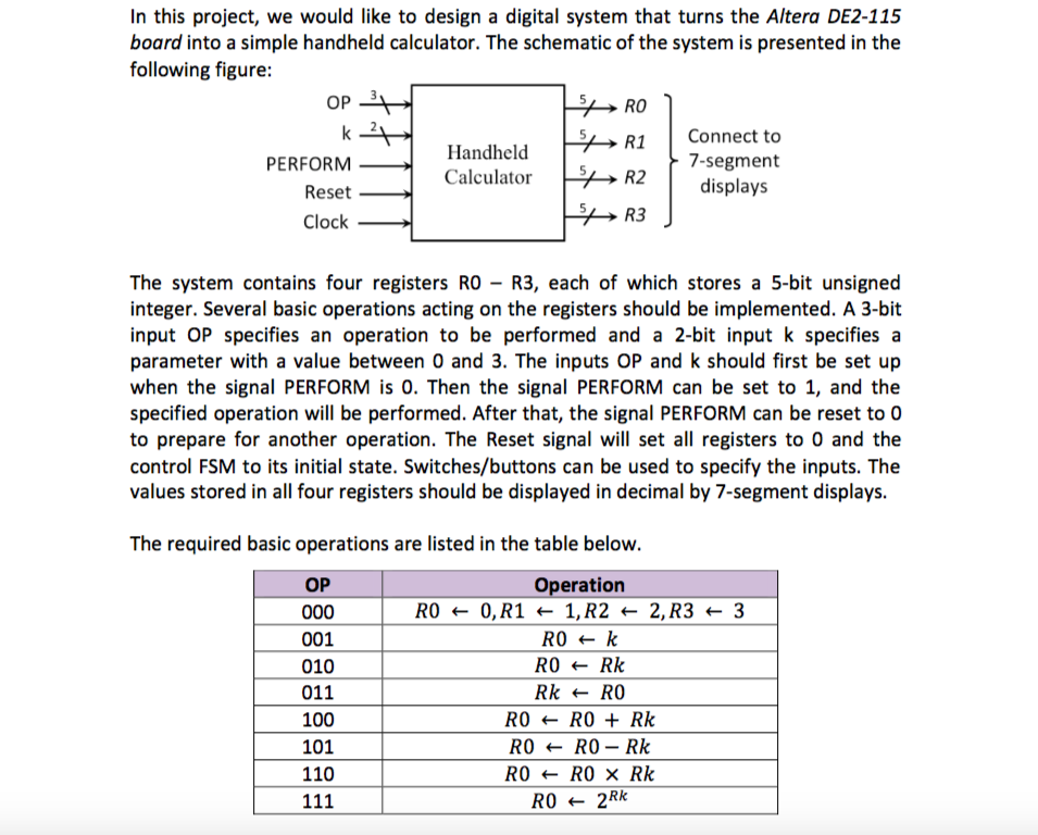
In this project, we would like to design a digital system that turns the Altera DE2-115 board into a simple handheld calculator. The schematic of the system is presented in the following figure: OP RO R1 Connect to R2 R3 PERFORM Reset Clock Handheld Calculator 7-segment displays The system contains four registers RO - R3, each of which stores a 5-bit unsigned integer. Several basic operations acting on the registers should be implemented. A 3-bit input OP specifies an operation to be performed and a 2-bit input k specifies a parameter with a value between 0 and 3. The inputs OP and k should first be set up when the signal PERFORM is 0. Then the signal PERFORM can be set to 1, and the specified operation will be performed. After that, the signal PERFORM can be reset to O to prepare for another operation. The Reset signal will set all registers to 0 and the control FSM to its initial state. Switches/buttons can be used to specify the inputs. The values stored in all four registers should be displayed in decimal by 7-segment displays. The required basic operations are listed in the table below. Operation RO + 0,R1 - 1,R2 - 2,R3 - '3 OP 001 010 011 100 101 110 RO - Rk Rk RO RO ROR RORO Rk In this project, we would like to design a digital system that turns the Altera DE2-115 board into a simple handheld calculator. The schematic of the system is presented in the following figure: OP RO R1 Connect to R2 R3 PERFORM Reset Clock Handheld Calculator 7-segment displays The system contains four registers RO - R3, each of which stores a 5-bit unsigned integer. Several basic operations acting on the registers should be implemented. A 3-bit input OP specifies an operation to be performed and a 2-bit input k specifies a parameter with a value between 0 and 3. The inputs OP and k should first be set up when the signal PERFORM is 0. Then the signal PERFORM can be set to 1, and the specified operation will be performed. After that, the signal PERFORM can be reset to O to prepare for another operation. The Reset signal will set all registers to 0 and the control FSM to its initial state. Switches/buttons can be used to specify the inputs. The values stored in all four registers should be displayed in decimal by 7-segment displays. The required basic operations are listed in the table below. Operation RO + 0,R1 - 1,R2 - 2,R3 - '3 OP 001 010 011 100 101 110 RO - Rk Rk RO RO ROR RORO Rk
Step by Step Solution
There are 3 Steps involved in it

Get step-by-step solutions from verified subject matter experts