

Question: I need help with this pre lab assignment? for electrical and computer science major PRE-LAB Pre-lab work must be completed individually prior to the lab


I need help with this pre lab assignment? for electrical and computer science major
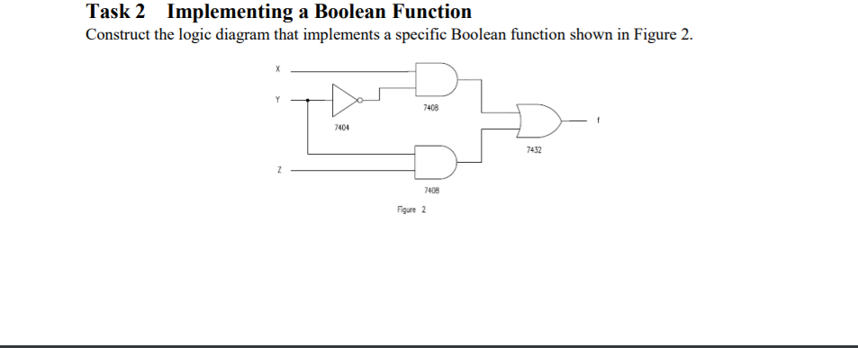
PRE-LAB Pre-lab work must be completed individually prior to the lab session. The pre-lab for this lab assignment will constitute 40% of your lab grade. You must deliver a hard copy documenting your individually per- formed pre-lab work to your lab instructor at the start ofyour scheduled lab session Task 1 Study the datasheets for the SN7408, SN7432, and SN7404 ICs. Note the number of logic gates in each IC packaging as well as the pin layout for each gate with particular emphasis on Vcc and GND pins for each IC. Determine how many logic gates each IC has along with pin numbers for inputs and outputs of each gate Task 2 Separately simulate each of the following logic gates using the WinLogiLab software . NOT gate . 2-input AND gate 2-input OR gate * Use the WinBoolean utility in WinLogiLab and choose the New Schematic option to get started. You may find the tutorial window in the bottom right to be helpful in learning how to use WinBoolean. Apply all possible logic combinations of inputs for a given logic gate and generate the corresponding output using the Digital Logic Tracer, which can be activated by choosing the Trace Logic through Circuit option under the Solve menu. Capture, save, and print the schematic and the corresponding tracer outputs to serve as records of having completed the preliminary work and for the lab report. Task 3 Simulate the logic circuit shown in Figure 2 using the WinBoolean utility. Determine the truth table for the function using the tracer utility and compare it with the truth table generated manually. Capture the sche- matic and tracer outputs to a file and hard copy printout. Task 4 Develop a test setup for the logic circuit in Figure 2 to generate and apply a proper set of inputs and to observe relevant outputs using the binary counter SN7493, the function generator, and the mixed-signal oscilloscope (MSO). Detail the settings for the function generator, minimum set of connections to the mixed-signal oscilloscope, and connections to the SN7493. Draw a logic schematic (using the WinLogiLab PRE-LAB Pre-lab work must be completed individually prior to the lab session. The pre-lab for this lab assignment will constitute 40% of your lab grade. You must deliver a hard copy documenting your individually per- formed pre-lab work to your lab instructor at the start ofyour scheduled lab session Task 1 Study the datasheets for the SN7408, SN7432, and SN7404 ICs. Note the number of logic gates in each IC packaging as well as the pin layout for each gate with particular emphasis on Vcc and GND pins for each IC. Determine how many logic gates each IC has along with pin numbers for inputs and outputs of each gate Task 2 Separately simulate each of the following logic gates using the WinLogiLab software . NOT gate . 2-input AND gate 2-input OR gate * Use the WinBoolean utility in WinLogiLab and choose the New Schematic option to get started. You may find the tutorial window in the bottom right to be helpful in learning how to use WinBoolean. Apply all possible logic combinations of inputs for a given logic gate and generate the corresponding output using the Digital Logic Tracer, which can be activated by choosing the Trace Logic through Circuit option under the Solve menu. Capture, save, and print the schematic and the corresponding tracer outputs to serve as records of having completed the preliminary work and for the lab report. Task 3 Simulate the logic circuit shown in Figure 2 using the WinBoolean utility. Determine the truth table for the function using the tracer utility and compare it with the truth table generated manually. Capture the sche- matic and tracer outputs to a file and hard copy printout. Task 4 Develop a test setup for the logic circuit in Figure 2 to generate and apply a proper set of inputs and to observe relevant outputs using the binary counter SN7493, the function generator, and the mixed-signal oscilloscope (MSO). Detail the settings for the function generator, minimum set of connections to the mixed-signal oscilloscope, and connections to the SN7493. Draw a logic schematic (using the WinLogiLab
Step by Step Solution
There are 3 Steps involved in it

Get step-by-step solutions from verified subject matter experts