

Question: i ) Q 2 Consider the truss shown in Fifure? Two loading rases are apnitied to the joints ( I ) 2 k g of
i
Q
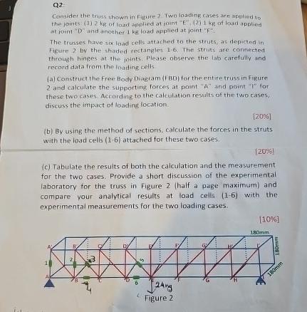
Consider the truss shown in Fifure? Two loading rases are apnitied to the joints I of load applied at iont of loari apptict at joint and another load applied at joint
The trussec have six laad cells attached to the struts, as depicted in Figure by the shaded rectangles The strits are connected through hinges at the joints. Please observe the lab carefully and Foord data from the loading cells
a Construct the Free Body Diagram FBO for the entire truss in Figure: and calculate the supporting forces at point and point for these two cases According, to the calculation results of the two cases, discuss the impact of loadinglocation.
b By using the method of sections, calculate the forces in the struts with the load cells attached for these two cases.
c Tabulate the results of both the calculation and the measurement for the two cases. Provide a short discussion of the experimental laboratory for the truss in Figure half a page maximum and compare vour analytical results at load cells with the experimental measurements for the two loading cases.
Step by Step Solution
There are 3 Steps involved in it
1 Expert Approved Answer
Step: 1 Unlock

Question Has Been Solved by an Expert!
Get step-by-step solutions from verified subject matter experts
Step: 2 Unlock
Step: 3 Unlock