

Question: Ve The circuit diagram of a three operational amplifier instrumentation amplifier is shown in Figure Q1(b). OP AMP 1 OP AMP 2 1-2 E
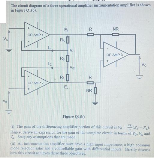
Ve The circuit diagram of a three operational amplifier instrumentation amplifier is shown in Figure Q1(b). OP AMP 1 OP AMP 2 1-2 E RAI RB RA E V. V.2 R R NR +1 NR ] OP AMP 3 Vo Figure Q1(b) NR = (i) The gain of the differencing amplifier portion of this circuit is Vo (E-E). R Hence, derive an expression for the gain of the complete circuit in terms of Vo. VA and V. State any assumptions that are made. (ii) An instrumentation amplifier must have a high input impedance, a high common mode rejection ratio and a controllable gain with differential inputs. Briefly discuss how this circuit achieves these three objectives.
Step by Step Solution
There are 3 Steps involved in it
Question 1 i To derive an expression for the gain of the complete circuit we can start with the gain ... View full answer

Get step-by-step solutions from verified subject matter experts