

Question: ii. Does not return anything 2. Electrical circuits may be connected in series or in parallel. You can read a general description at https://www.allaboutcircuits.com/textbook direct-current
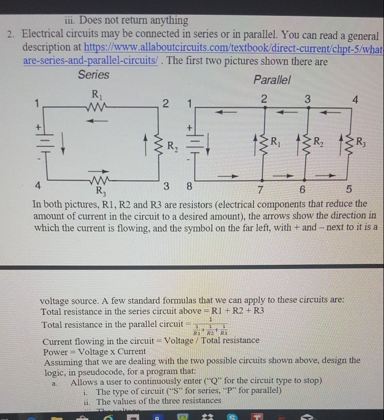
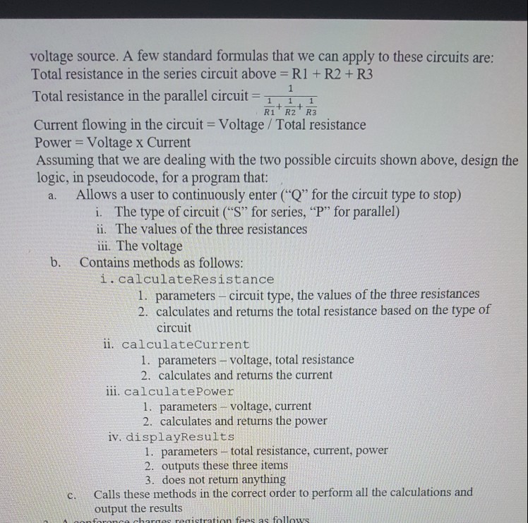
ii. Does not return anything 2. Electrical circuits may be connected in series or in parallel. You can read a general description at https://www.allaboutcircuits.com/textbook direct-current chpt-5/what are-series-and-parallel-circuits/. The first two pictures shown there are Series Parallel R, 2 3 4 R, 4 3 8 5 In both pictures, R1, R2 and R3 are resistors (electrical components that reduce the amount of current in the circuit to a desired amount), the arrows show the direction in which the current is flowing, and the symbol on the far left, with + and -next to it is a voltage source. A few standard formulas that we can apply to these circuits are: Total resistance in the series circuit above R1 +R2 +R3 Total resistance in the parallel circuit1 R1 R2 R3 Current flowing in the circuit Voltage Total resistance Power = Voltage x Current Assuming that we are dealing with the two possible circuits shown above, design the logic, in pseudocode, for a program that: a. Allows a user to continuously enter ("Q" for the circuit type to stop) i. The type of circuit ("S" for series, "P" for parallel) ii. The values of the three resistances
Step by Step Solution
There are 3 Steps involved in it

Get step-by-step solutions from verified subject matter experts