

Question: II . RL Circuit Figure 2 : Circuit 2 - RL Circuit Construct the circuit in Figure 2 . Set up the oscilloscope in the
II RL Circuit
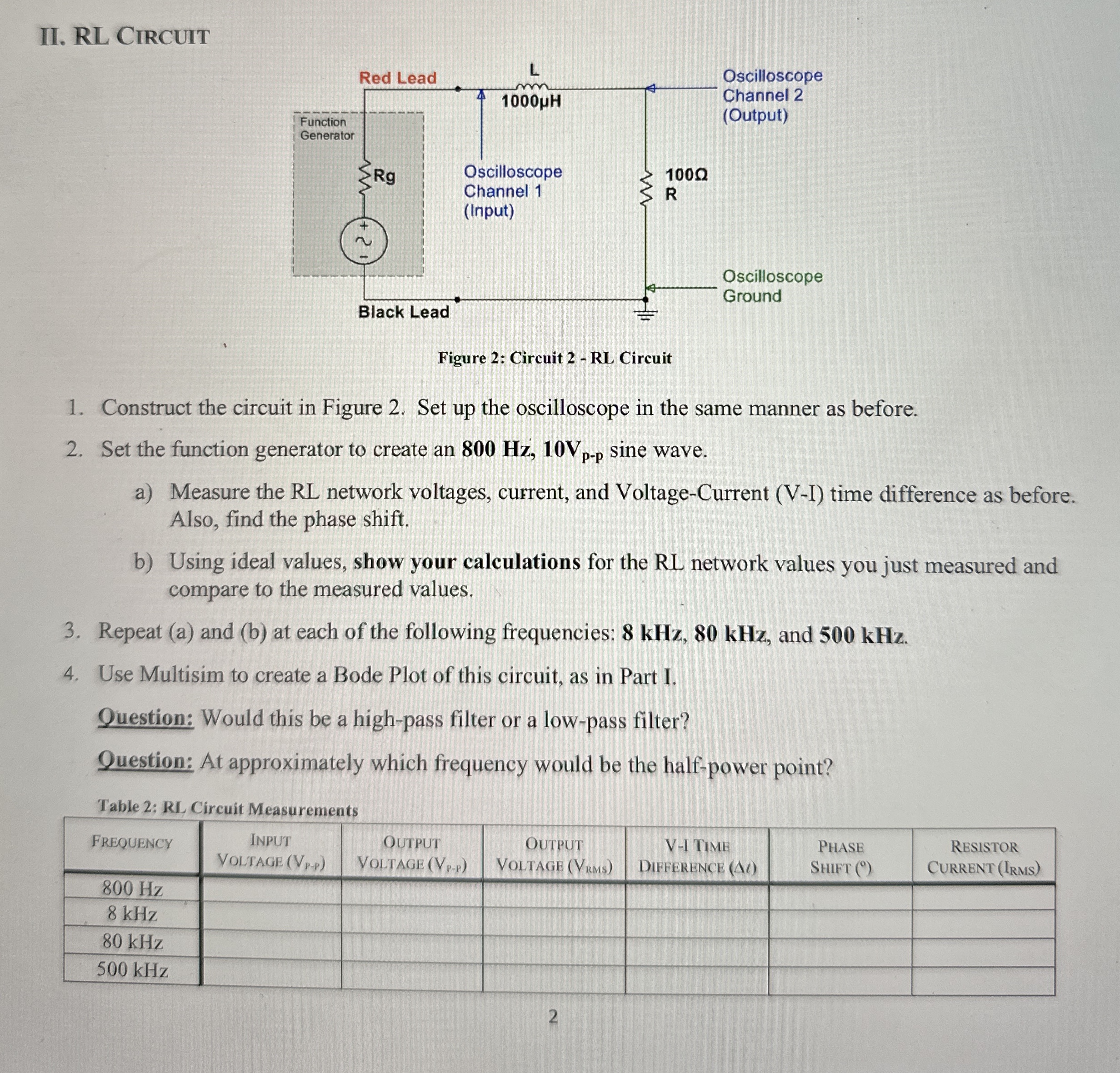
Figure : Circuit RL Circuit
Construct the circuit in Figure Set up the oscilloscope in the same manner as before.
Set the function generator to create an sine wave.
a Measure the RL network voltages, current, and VoltageCurrent VI time difference as before. Also, find the phase shift.
b Using ideal values, show your calculations for the RL network values you just measured and compare to the measured values.
Repeat a and b at each of the following frequencies: and
Use Multisim to create a Bode Plot of this circuit, as in Part I.
Question: Would this be a highpass filter or a lowpass filter?
Question: At approximately which frequency would be the halfpower point?
Table : RL Circuit Measurements
tableFrequencytableInPut
Step by Step Solution
There are 3 Steps involved in it
1 Expert Approved Answer
Step: 1 Unlock

Question Has Been Solved by an Expert!
Get step-by-step solutions from verified subject matter experts
Step: 2 Unlock
Step: 3 Unlock