

Question: Implement a finite state machine using JK flip-flops, consider the given state transition diagram shown in figure 4 for a finite state machine with one
Implement a finite state machine using JK flip-flops, consider the given state transition diagram shown in figure 4 for a finite state machine with one input bit and one output bit: Assume that the state assignments are 00 for S0, 01 for S1, 10 for S2, 11 for S3. Use X and Y variables to represent the input and the output, respectively as (X/Y). Simplify the Boolean expression/function using Karnaugh maps for JK inputs to each JK-flip flop and for the output, y. Finally, design a circuit based on the simplified values of each JK flip flop and Y.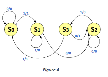
0/0 1/1 1/0 So S1 S3 S2 0/1 1/0 0/0 0/0 1/1 Figure 4
Step by Step Solution
There are 3 Steps involved in it
1 Expert Approved Answer
Step: 1 Unlock

Question Has Been Solved by an Expert!
Get step-by-step solutions from verified subject matter experts
Step: 2 Unlock
Step: 3 Unlock