

Question: * ( Important ) * * Please solve this problem in detail and make sure to draw the state diagram of FSM and solve the
ImportantPlease solve this problem in detail and make sure to draw the state diagram of FSM and solve the verilog HDL codeWe would like to design a prime number checker that works as shown in Figure
Figure
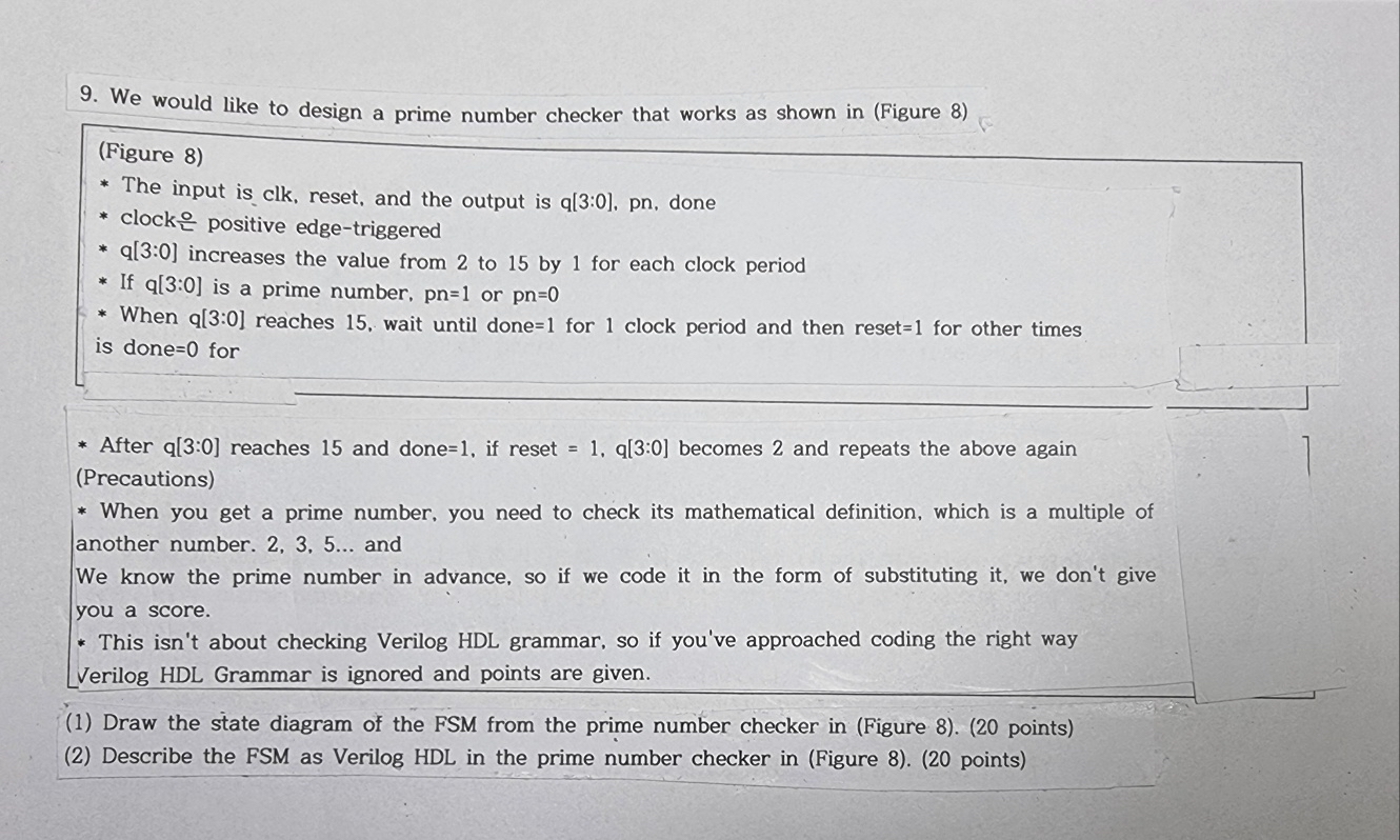
The input is clk reset, and the output is q: pn done
clock positive edgetriggered
: increases the value from to by for each clock period
If : is a prime number, or
When : reaches wait until done for clock period and then reset for other times is done for
After : reaches and done if reset : becomes and repeats the above again Precautions
When you get a prime number, you need to check its mathematical definition, which is a multiple of another number. and
We know the prime number in advance, so if we code it in the form of substituting it we don't give you a score.
This isn't about checking Verilog HDL grammar, so if you've approached coding the right way Verilog HDL Grammar is ignored and points are given.
Draw the state diagram of the FSM from the prime number checker in Figure points
Describe the FSM as Verilog HDL in the prime number checker in Figure points
Step by Step Solution
There are 3 Steps involved in it
1 Expert Approved Answer
Step: 1 Unlock

Question Has Been Solved by an Expert!
Get step-by-step solutions from verified subject matter experts
Step: 2 Unlock
Step: 3 Unlock