

Question: In this particular register configuration, data is simultaneously inputted and outputted in parallel. All four flip flops within the register are synchronized by both the
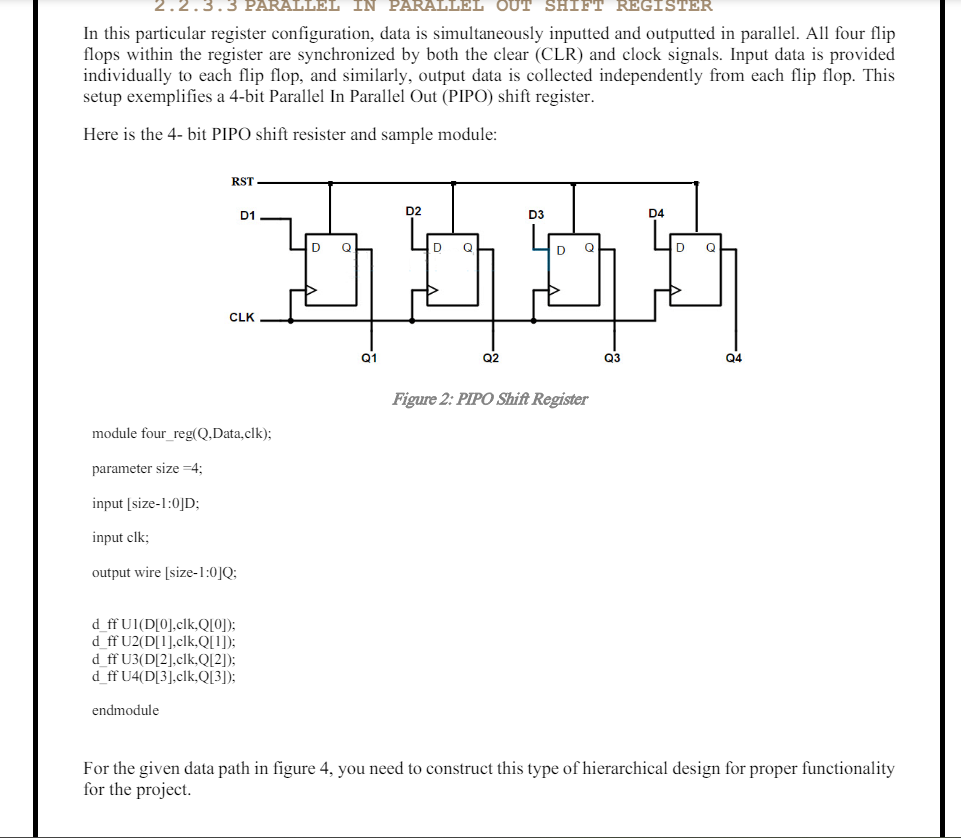
In this particular register configuration, data is simultaneously inputted and outputted in parallel. All four flip
flops within the register are synchronized by both the clear CLR and clock signals. Input data is provided
individually to each flip flop, and similarly, output data is collected independently from each flip flop. This
setup exemplifies a bit Parallel In Parallel Out PIPO shift register.
Here is the bit PIPO shift resister and sample module:
module fourregQData,clk;
parameter size ;
input size:D;
input clk;
output wire size:Q;
dff UlDclkQ;
dff UDclkQ;
dff UDclkQ;
dff UDclkQ;
endmodule
For the given data path in figure you need to construct this type of hierarchical design for proper functionality
for the project.
Step by Step Solution
There are 3 Steps involved in it
1 Expert Approved Answer
Step: 1 Unlock

Question Has Been Solved by an Expert!
Get step-by-step solutions from verified subject matter experts
Step: 2 Unlock
Step: 3 Unlock