

Question: Include a 2-input NAND gate in the register of Fig. 6.1 and connect the gate output to the C inputs of all the flip-flops. One
Include a 2-input NAND gate in the register of Fig. 6.1 and connect the gate output to the C inputs of all the flip-flops. One input of the NAND gate receives the clock pulses from the clock generator, and the other input of the NAND gate provides a parallel load control. Explain the operation of the modified register. Explain why this circuit might have operational problems.
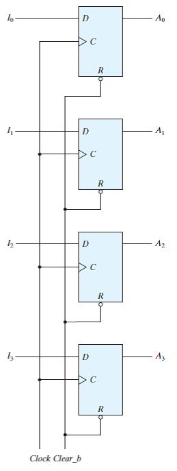
Include a 2-input NAND gate in the register of Fig. 6.1 and connect the gate output to the C inputs of all the flip-flops. One input of the NAND gate receives the clock pulses from the clock generator, and the other input of the NAND gate provides a parallel load control. Explain the operation of the modified register. Explain why this circuit might have operational problems. Ap A, A2 Clock Clear_b
Step by Step Solution
3.45 Rating (165 Votes )
There are 3 Steps involved in it
Modified Register Operation 1 NAND Gate Integration A 2input NAND gate is added One input is connected to the clock pulses from the clock generator an... View full answer

Get step-by-step solutions from verified subject matter experts