

Question: input scope Fig. (5-2): Matlab and Simulink representation. input scope Fig. (5-3): Matlab and Simulink representation. input scope Fig. (5-4): Matlab and Simulink representation. 3
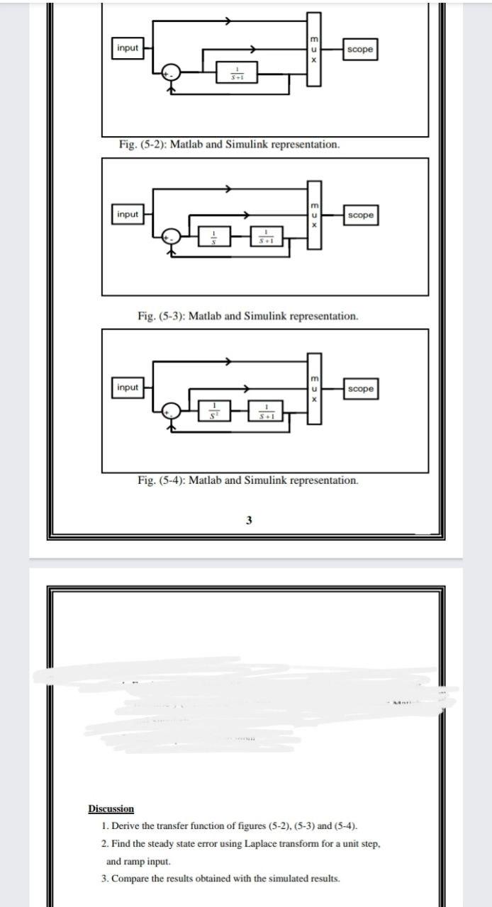
input scope Fig. (5-2): Matlab and Simulink representation. input scope Fig. (5-3): Matlab and Simulink representation. input scope Fig. (5-4): Matlab and Simulink representation. 3 Discussion 1. Derive the transfer function of figures (5-2), (5-3) and (5-4). 2. Find the steady state error using Laplace transform for a unit step, and ramp input. 3. Compare the results obtained with the simulated results
Step by Step Solution
There are 3 Steps involved in it
1 Expert Approved Answer
Step: 1 Unlock

Question Has Been Solved by an Expert!
Get step-by-step solutions from verified subject matter experts
Step: 2 Unlock
Step: 3 Unlock