

Question: IP Addressing Table: VLSM Subnets Required Users Desc Subnetwork Broadcast IPv6 CIDR Point-to-Point Point-to-Point Point-to-Point Point-to-Point PC - A PC - B PC - C
| IP Addressing Table: VLSM Subnets | |||||
| Required Users | Desc | Subnetwork | Broadcast | IPv6 | CIDR |
|
|
|
|
|
|
|
|
|
|
|
|
|
|
|
|
|
|
|
|
|
|
|
|
|
|
|
|
|
|
|
|
|
|
|
|
|
|
|
|
|
|
| Point-to-Point |
|
|
|
|
|
| Point-to-Point |
|
|
|
|
|
| Point-to-Point |
|
|
|
|
|
| Point-to-Point |
|
|
|
|
|
| PC - A | PC - B | PC - C | |
| VLAN |
|
|
|
| IPv4 Address |
|
|
|
| Subnet Mask |
|
|
|
| V4 Gateway |
|
|
|
| IPv6 Address |
|
|
|
| IPv6 Gateway |
|
|
|
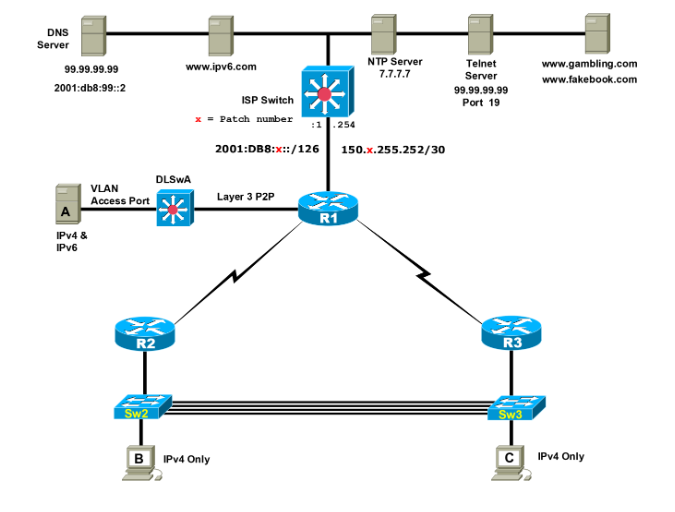
Practice Skills CCNA 2 Directions: Configuring three routers R1, R2, and R3, three Catalyst switches and three PCs. Initial Core Configuration: 70 points Use the network address of 172.XX.128.0 / 22 and 2001:db8:x:aXX0::/60. Configure IPv6 LANs to use a /64 CIDR and IPv6 WAN links are pointtopoint links so use a /126. Use EIGRP for IPv4 and IPv6. XX = your 2 digit number. Configure a housekeeping script on each device. Important: Some tasks may be necessary for functionality but may not be explicitly stated. Additionally, this lab may not reflect networking best practices. R1 1. Connect to the ISP via the Gigabit 0/0 interface based on the Topology diagram 2. Configure a static default route via the Gigabit link to the ISP which will set a Gateway of Last Resort. a. Set the default static IPv4 route so ARP broadcasts are not sent for each unknown IP address. 3. Configure NAT-PAT. Configure routing between R1, DLSwA, R2 and R3. a. Propagate an IPv4 Gateway of Last Resort from R1 to DLSwA, R2 and R3. 4. Set a static default IPv6 route to the ISP. Configure IPv6 EIGRP between R1 & DLSwA. a. Propagate an IPv6 default route to DLSwA and R3. R2 R3 Subinterfaces 1. Configure the Ethernet link between R2 and R3 using subinterfaces. 2. Configure PC B subnet in VLAN 300 to support 300 users 3. Configure PC C subnet in VLAN 100 to support 100 users 4. Configure the Mgmt VLAN on VLAN 999 using a 26 bit mask. 5. Connect R2 Gigabit 0/0 to Port 24 on Sw2 and connect R3 Gigabit 0/0 to port 24 on Sw3. 802.1Q Trunking 1. Configure port 24 on Sw2 and Sw3 trunking. 2. Configure four 802.1Q trunk links between Sw2 and Sw3 on FastEthernet ports 1 and 2 and on GigabEthernet ports 1 and 2. DLSwA 1. Configure port 24 as a layer 3 pointtopoint link to R1. 2. Configure VLAN 888 and name the VLAN PCA a. Configure the subnet to support 57 users 3. Configure an SVI to provide gateway services to PCA in VLAN 888 for IPv4 and IPv6 First Hop Redundancy Protocol (FHRP) 1. Enable FHRP on subinterfaces; allow redundancy on each subinterface 2. Configure R2 as Active GW for PCB and R3 as the Active GW for PCC PCA & PCB 1. Configure PCA with a static IPv4 and IPv6 address using SLACC in VLAN 888 on Port 10 2. Allow PCB to use DHCP in VLAN 300 on S2 Port 10 3. Allow PCC to use DHCP in VLAN 100 on S3 Port 10 PC Connectivity using DNS Value of 70 Points 1. Verify PING between PCA and PCB. Then have PCA HTTP to www.gambling.com 2. From PCA via IPv6 www.ipv6.com 3. HTTP from PCB with redundancy to www.fakebook.com 4. HTTP from PCC to www.gambling.com CCNA 2 - SRWE v7 Page 2 of 2 Brooks Practice Skills Additional Tasks for Additional Point Values Some of the following tasks are assigned a specific point value. Points are awarded if the solution meets all of the requirements and does not violate any preset restrictions. Some tasks may have multiple solutions so as long as the solution meets the given requirements, points will be awarded for that task. Note that some solutions may have a negative impact to previous or future tasks and any console error messages will have points deducted. Additionally, no partial credit is awarded for any task. Only Port 24 on Sw2 & Sw3 1. Use Native VLAN 1001 Floating IPv6 Static Routes 1. Create a floating default IPv4 and IPv6 static route on DLSwA to R1 2. Create a floating IPv4 and IPv6 static route on R1 to DLSwA for PCA subnet. Trunking 1. Configure trunking on FastEthernet ports between Sw2 and Sw3 using native VLAN 123 2. Configure trunking on Gigabit ports between Sw2 and Sw3 using native VLAN 456 IPv6 DHCP 1. Allow PCA to dynamically receive an IPv6 address via stateful DHCP a. Set the domain name to Stateful.DHCP.pca STP 1. Ensure Sw2 is the root for VLAN 300 and Sw3 is the root for VLAN 100 2. Configure Sw2 and Sw3 switches to use 802.1s 3. Statically set the STP priority of VLAN 300 on Sw3 to its highest possible value. EtherChannel 1. Configure EtherChannel using PAgP on the FastEthernet ports. 2. Configure EtherChannel using LACP on the Gig ports Port Security 1. Set Port Security on Sw2 & statically set the MAC address of PCB on port Fa0/10 2. Configure Port Security so if a second MAC address is learned on Port 10 the port will not be err-disabled and a console message will be displayed. SSH Management VLAN 1. Only allow PCA to SSH via any IPv4 on DLSwA a. Do not allow version 1 b. Specify the username SSH & Type 9 password of TCPPORT22 c. Set the ssh timeout to 20 seconds d. Only allow two failed attempts before disconnecting the SSH session BPDU Guard 1. Enable BPDU guard on PCA & PCB access ports
Step by Step Solution
There are 3 Steps involved in it

Get step-by-step solutions from verified subject matter experts