

Question: LAB 1 - STM 3 2 : Digital IO - LED and Pushbutton and TIMER Introduction This lab uses a STM 3 2 G 0
LAB STM: Digital IO LED and Pushbutton and TIMER Introduction
This lab uses a STMGRBT
Objectives
To install and setup STMCubeIDE on your machine, which is essential to complete the lab tasks and the MCU project
To configure the GPIO registers within the STM to blink an LED that is controlled by reading an input from a pushbutton
To explore some basic debugging strategies in embedded systems
Activity #: Preparation
Read through section of the STMG datasheet.
Follow the guide "Getting Started on STM CubeIDE" and follow the steps to blink the LED at Hz
If the onboard LED is blinking at Hz your system is ready for the lab.
Activity #: Control an LED using a pushbutton
Modify the code to blink the onboard LED at Hz or ON for sec and OFF for sec while the user pushbutton is pressed.
While the button is released, turn off the LED.
In your setup code, configure the port and pin connected to the user button builtin push button as an input
Determine which port and pin the button is connected to in section of the STM Nucleo board's user manual
Enable the clock to that port
Configure the pin to be an input
Determine if you should configure a pullup or pulldown resistor using GPIOxPUPDR
In your main loop, read the value of the corresponding bit in GPIOxIDR.
To check a bit, you can use the following:
if GPIOxIDR n &
Runs if the nth bit of GPIOxIDR is set
Activity #: Using the BSR
An alternative way of setting the output of a pin to be HIGH or LOW is to use the bit set reset register. Refer to section and of the datasheet.
In your code, instead of using the output data register ODR use the bit set reset register BSRR to turn on and off the LED.
Activity #: Delay Function using TIM in Count up Overflow Mode
Configure TIM to overflow every ms in count up mode to create your own HAL delay function. This is done by enabling TIM and setting the prescaler PSC and autoreload value ARR It is recommended to read up on Chapter of the datasheet to understand the principles of different counter modes.
The instructions to do so are as follows.
Enable TIM in the Reset and Clock Control
Set TIM in count up mode.
Set the Prescaler PSC and AutoReload Register ARR values.
Enable TIM on the Control Register.
Use TIM to generate your own HAL delay function.
To set the PSC and ARR values, the following relationship needs to be used.
Fevents FCLK PSC ARR
Where the Fclk is the frequency of the system clock defined by the APB Timer Clocks in CubeIDEs clock configuration. The overflow value is set by the ARR.
The delay function should have a similar format to what is shown. Call this function in
the main while loop and set a delay value in milliseconds
void mydelaymsuintt ms
Read from TIM counter and increment a variable.
Clear the status register and repeat until the millisval.
TIMSR & ~;
Appendices
Appendix : Setting up Timer TIM
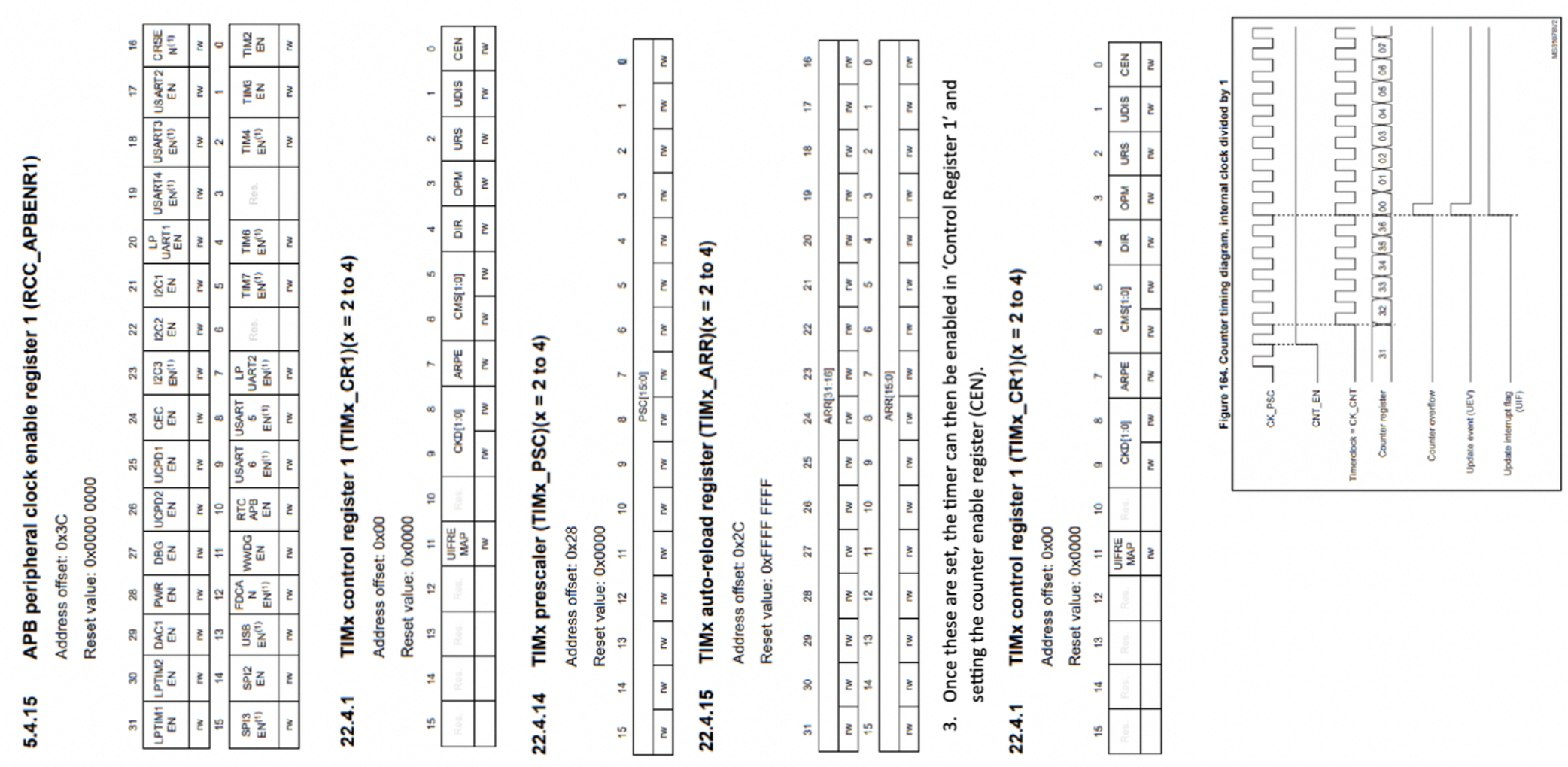
Enable the TIM register in the APB peripheral clock enable register RCCAPBENR The relevant information can be found in Chapter of the datasheet. To better understand how count up timers work, refer to Chapter and in the
Datasheet.
The STM architecture has multiple timer signals that you can configure. By enabling
the clock for RCCAPBENR additional registers need to be set based on the purpose of the timer. These can be found in Chapter of the datasheet. To configure the TIM Registers, the following procedure should be followed.
The timer must be set to count up mode. This is done by configuring control register and setting the Direction register. Refer to Chapter in the datasheet.
Set the prescaler PSC and AutoReload Values ARR The PSC and ARR values are set based on the required time interval and have the following relationship.
Fevents FCLK PSC ARR
Where Fclk comes from the ABP peripheral clock, event frequency is how
frequent the timer increments. The prescaler is used to divide the clock signal
while the ARR is the maximum value to set for timer overflow. PSC and ARR
register values, in Chapters and of the datasheet.
Once these are set, the timer can then be enabled in Control Register and setting the counter enable register CENThe count up diagram found in Chapter in the datasheet explains the timer operations. To generate the delay needed in the timer, an update event needs to occur, ie when a counter overflows. This triggers an interrupt flag which needs to be read and reset. : Compared to AVR, this is an indicator this is an overflow has occured.
Step by Step Solution
There are 3 Steps involved in it
1 Expert Approved Answer
Step: 1 Unlock

Question Has Been Solved by an Expert!
Get step-by-step solutions from verified subject matter experts
Step: 2 Unlock
Step: 3 Unlock