

Question: Lab 4B - RFALU with Data Memory (RFALUDM) - Load Operation When a computer boots up, it will load operating system and instructions from the
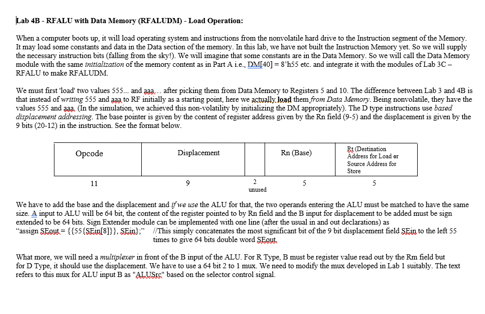
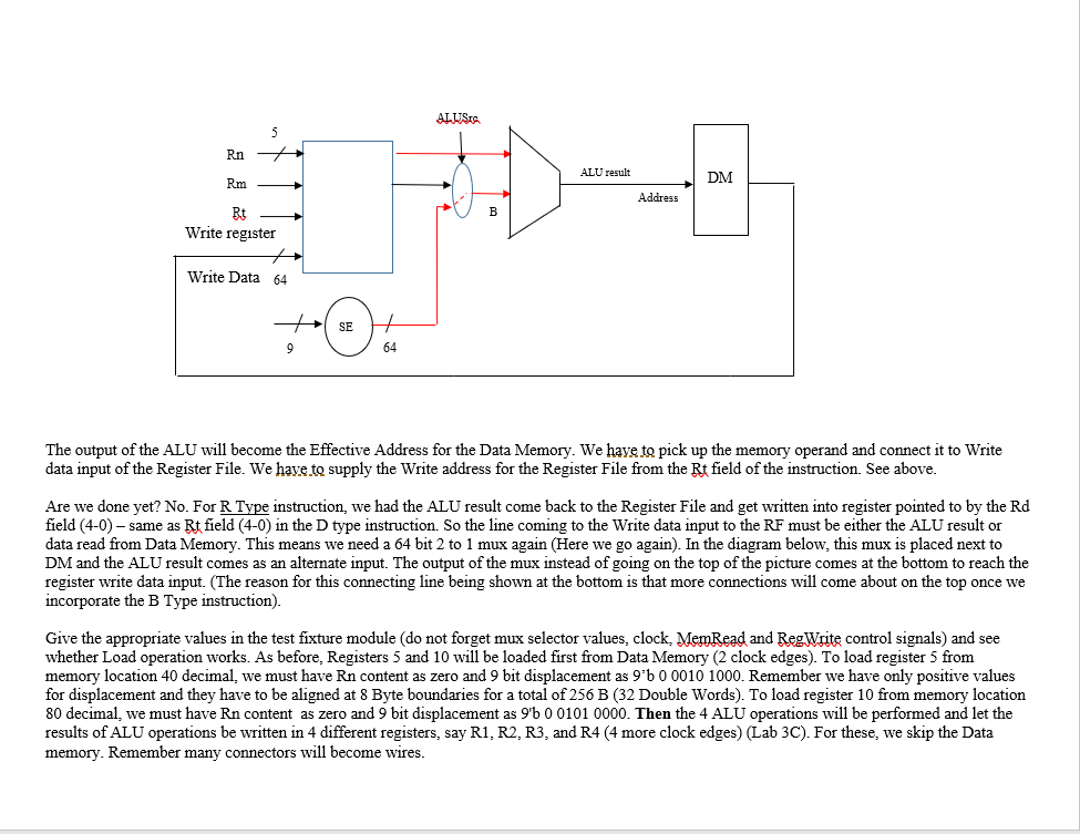
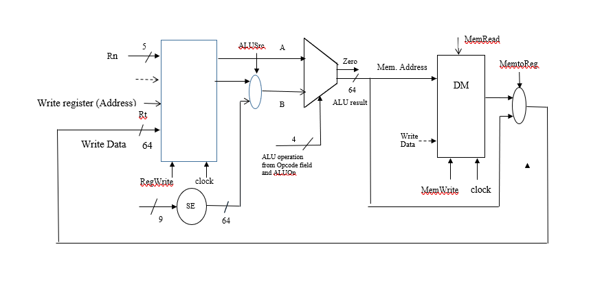
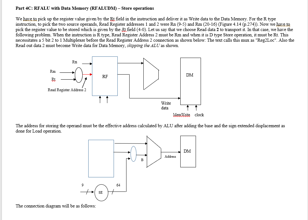
Lab 4B - RFALU with Data Memory (RFALUDM) - Load Operation When a computer boots up, it will load operating system and instructions from the nonvolatile hard drive to the Instruction segment of the Memory It may load some constants and data in the Data section of the memory. In this lab, we have not built the Instruction Memory yet. So we will supply the necessary instruction bits (falling from the sky!). We will imagine that some constants are in the Data Memory. So we will call the Data Memory module with the same initialization of the memory content as in Part A 1L., DM[40] = 8h55 etc and integrate it with the modules of Lab 3C- RFALU to make RFALUDM. We must first 'load' two values 555... and aaa... after picking them from Data Memory to Registers 5 and 10. The difference between Lab 3 and 4B is that instead of writing 555 and aaa to RF initially as a starting point, here we actually.load them from Data Memory. Being nonvolatile, they have the values 555 and aaa, (In the simulation, we achieved this non-volatility by initializing the DM appropriately). The D type instructions use based displacement addressing. The base pointer is given by the content of register address given by the Rn field (9-5) and the displacement is given by the 9 bits (20-12) in the instruction. See the format below Bt (Destination Address for Load or Source Address for Store code Displacement Rn (Base) unused We have to add the base and the displacement and ifwe use the ALU for that, the two operands entering the ALU must be matched to have the same size. A input to ALU will be 64 bit, the content of the register pointed to by Rn field and the B input for displacement to be added must be sign extended to be 64 bits. Sign Extender module can be implemented with one line (after the usual in and out declarations) as "assign SFaut = { {55 {SEin[3] } } SEn) /This simply concatenates the most significant bit of the 9 bit displacement field SEin to the left 55 times to give 64 bits double word SEgut, What more, we will need a multiplexer in front of the B input of the ALU. For R Type, B must be register value read out by the Rm field but for D Type, it should use the displacement. We have to use a 64 bit 2 to 1 mux. We need to modify the mux developed in Lab 1 suitably. The text refers to this mux for ALU input B as "ALUSr" based on the selector control signal. Lab 4B - RFALU with Data Memory (RFALUDM) - Load Operation When a computer boots up, it will load operating system and instructions from the nonvolatile hard drive to the Instruction segment of the Memory It may load some constants and data in the Data section of the memory. In this lab, we have not built the Instruction Memory yet. So we will supply the necessary instruction bits (falling from the sky!). We will imagine that some constants are in the Data Memory. So we will call the Data Memory module with the same initialization of the memory content as in Part A 1L., DM[40] = 8h55 etc and integrate it with the modules of Lab 3C- RFALU to make RFALUDM. We must first 'load' two values 555... and aaa... after picking them from Data Memory to Registers 5 and 10. The difference between Lab 3 and 4B is that instead of writing 555 and aaa to RF initially as a starting point, here we actually.load them from Data Memory. Being nonvolatile, they have the values 555 and aaa, (In the simulation, we achieved this non-volatility by initializing the DM appropriately). The D type instructions use based displacement addressing. The base pointer is given by the content of register address given by the Rn field (9-5) and the displacement is given by the 9 bits (20-12) in the instruction. See the format below Bt (Destination Address for Load or Source Address for Store code Displacement Rn (Base) unused We have to add the base and the displacement and ifwe use the ALU for that, the two operands entering the ALU must be matched to have the same size. A input to ALU will be 64 bit, the content of the register pointed to by Rn field and the B input for displacement to be added must be sign extended to be 64 bits. Sign Extender module can be implemented with one line (after the usual in and out declarations) as "assign SFaut = { {55 {SEin[3] } } SEn) /This simply concatenates the most significant bit of the 9 bit displacement field SEin to the left 55 times to give 64 bits double word SEgut, What more, we will need a multiplexer in front of the B input of the ALU. For R Type, B must be register value read out by the Rm field but for D Type, it should use the displacement. We have to use a 64 bit 2 to 1 mux. We need to modify the mux developed in Lab 1 suitably. The text refers to this mux for ALU input B as "ALUSr" based on the selector control signal
Step by Step Solution
There are 3 Steps involved in it

Get step-by-step solutions from verified subject matter experts