

Question: LEARNING OBJECTIVES: Connect the devices in the standard lab setup Connect the devices Verify connectivity View the standard lab setup in the Physical Workspace Enter
LEARNING OBJECTIVES:
Connect the devices in the standard lab setup
Connect the devices
Verify connectivity
View the standard lab setup in the Physical Workspace
Enter and view the Physical Workspace
View the standard lab setup at the various levels of the Physical Workspace
INTRODUCTION:
When working in Packet Tracer, in a lab environment, or in a corporate setting it is important to know how to select the proper cable and how to properly connect devices. This activity will examine device configurations in Packet Tracer, selecting the proper cable based on the configuration, and connecting the devices. This activity will also explore the physical view of the network in Packet Tracer
Task 1: Connect the devices in the standard lab setup
Step 1 Connect the devices
Connect PC 1 to the last port of switch S1 and PC 2 to the last port on switch S2 using the proper cable.
Click on router R1 and examine the configuration using the Config tab. Connect the proper interface on the router to Interface FastEthernet0/0 on switch S1 using the proper cable.
Connect the proper interface on the router to Interface FastEthernet0/1 on switch S2 using the proper cable.
Click on both routers and examine the configuration using the Config tab. Connect the routers together using the proper interfaces and the proper cable.
Click on router R2 and examine the configuration using the Config tab. Connect the proper interface on the router to the proper interface on Server using the proper cable.
Step 2 Verify connectivity-
From the Command Prompt on the Desktop of both PCs issue the command ping 192.168.254.254, the IP address of Server. If the pings fail, check your connections and troubleshoot until the pings succeed. Check your configuration by clicking the Check Results button.
Task 2: View the standard lab setup in the Physical Workspace- 5 Points
Step 1 - Enter and view the Physical Workspace
Most of our work in Packet Tracer has been done in the Logical Workspace. In an internetwork, routers may be in different sites from across the street to across the globe. The serial link between the routers represents a dedicated leased line between two locations consisting of a DTE (Data Terminal Equipment), such as a router, connected to a DCE (Data Communication Equipment), such as a CSU/DSU or modem. The DCE connects to a service provider's local loop and the connections are repeated at the other end of the link. The Physical Workspace allows us to see these relationships more clearly. Enter the Physical Workspace by clicking the tab in the upper left hand corner of the Workspace.
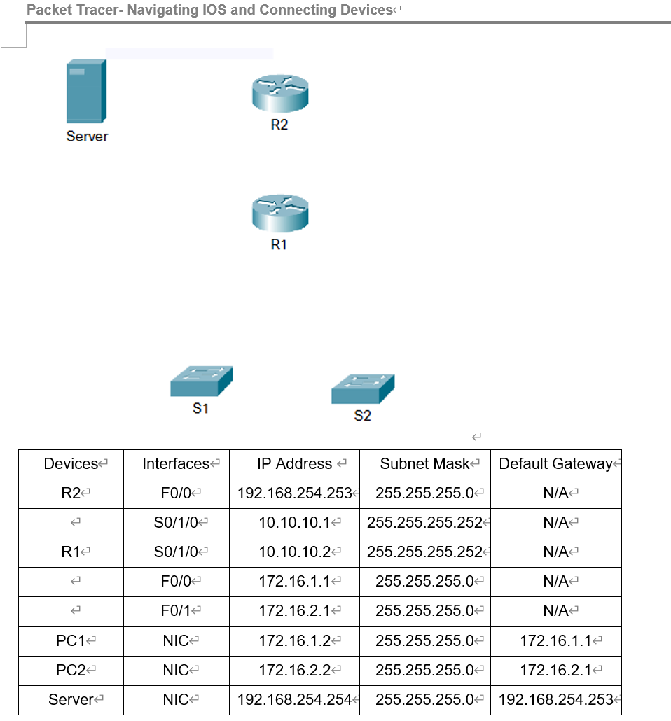
Packet Tracer- Navigating IOS and Connecting Devices Server R2 R1 S1 S2 \begin{tabular}{|c|c|c|c|c|} \hline Devices & Interfaces & IP Address & Subnet Mask & Default Gateway \\ \hline R2 & F0/0 & 192.168.254.253 & 255.255.255.0 & N/A \\ \hline & S0/1/0 & 10.10.10.1 & 255.255.255.252 & N/A \\ \hline R1 & S0/1/0 & 10.10.10.2 & 255.255.255.252 & N/A \\ \hline & F0/0 & 172.16.1.1 & 255.255.255.0 & N/A \\ \hline & F0/1 & 172.16.2.1 & 255.255.255.0 & N/A \\ \hline PC1 & NIC & 172.16.1.2 & 255.255.255.0 & 172.16.1.1 \\ \hline PC2 & NIC & 172.16.2.2 & 255.255.255.0 & 172.16.2.1 \\ \hline Server & NIC & 192.168.254.254 & 255.255.255.0 & 192.168.254.253 \\ \hline \end{tabular}
Step by Step Solution
There are 3 Steps involved in it

Get step-by-step solutions from verified subject matter experts