

Question: Make a lab from this lecture Inter-VLAN Routing Now you know how to segment and organize your network into VLANs. Hosts can communicate with other
Make a lab from this lecture
Inter-VLAN Routing Now you know how to segment and organize your network into VLANs. Hosts can communicate with other hosts in the same VLAN, and you no longer have hosts sending out broadcast messages to every other device in your network, eating up needed bandwidth. But what if a host in one VLAN needs to communicate with a host in a different VLAN? If you are a network administrator, you know that people will want to communicate with other people outside of your network. This is where inter-VLAN routing can help you.
VLANs are used to segment switched Layer 2 networks for a variety of reasons. Regardless of the reason, hosts in one VLAN cannot communicate with hosts in another VLAN unless there is a router or a Layer 3 switch to provide routing services.
There are two inter-VLAN routing options: Legacy Inter-VLAN routing - This is a legacy solution. It does not scale well. Router-on-a-Stick - This is an acceptable solution for a small to medium-sized network.
Legacy Inter-VLAN Routing The first inter-VLAN routing solution relied on using a router with multiple Ethernet interfaces. Each router interface was connected to a switch port in different VLANs. The router interfaces served as the default gateways to the local hosts on the VLAN subnet. For example, refer to the topology where R1 has two interfaces connected to switch S1.
Inter-VLAN routing is the process of forwarding network traffic from one VLAN to another VLAN.
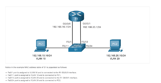 When PC1 sends a packet to PC2 on another network, it forwards it to its default gateway 192.168.10.1. R1 receives the packet on its G0/0/0 interface and examines the destination address of the packet. R1 then routes the packet out its G0/0/1 interface to the F0/12 port in VLAN 20 on S1. Finally, S1 forwards the frame to PC2. Legacy inter-VLAN routing using physical interfaces works, but it has a significant limitation. It is not reasonably scalable because routers have a limited number of physical interfaces. Requiring one physical router interface per VLAN quickly exhausts the physical interface capacity of a router. In our example, R1 required two separate Ethernet interfaces to route between VLAN 10 and VLAN 20. What if there were six (or more) VLANs to interconnect? A separate interface would be required for each VLAN. Obviously, this solution is not scalable.
Router-on-a-Stick Inter-VLAN Routing The router-on-a-stick inter-VLAN routing method overcomes the limitation of the legacy inter-VLAN routing method. It only requires one physical Ethernet interface to route traffic between multiple VLANs on a network. A Cisco IOS router Ethernet interface is configured as an 802.1Q trunk and connected to a trunk port on a Layer 2 switch. Specifically, the router interface is configured using subinterfaces to identify routable VLANs. The configured subinterfaces are software-based virtual interfaces. Each is associated with a single physical Ethernet interface. Subinterfaces are configured in software on a router. Each subinterface is independently configured with an IP address and VLAN assignment. Subinterfaces are configured for different subnets that correspond to their VLAN assignment. This facilitates logical routing. When VLAN-tagged traffic enters the router interface, it is forwarded to the VLAN subinterface. After a routing decision is made based on the destination IP network address, the router determines the exit interface for the traffic. If the exit interface is configured as an 802.Q subinterface, the data frames are VLAN-tagged with the new VLAN and sent back out the physical interface.
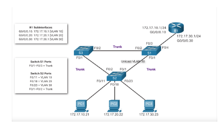
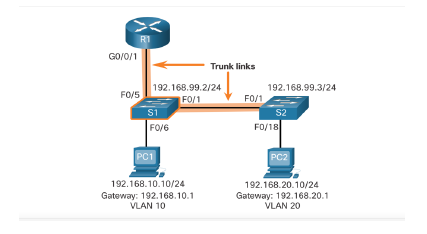
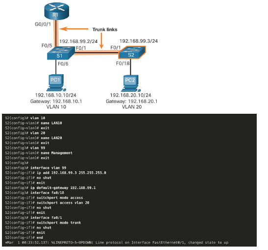
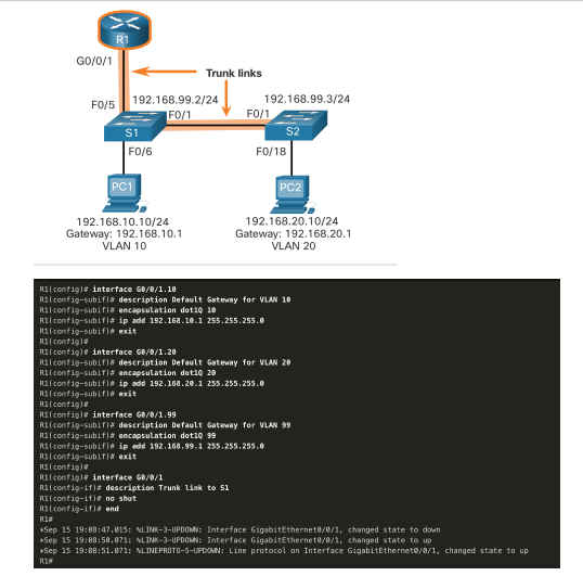
Router-on-a-Stick Scenario In the previous topic, three different ways to create inter-VLAN routing were listed, and legacy inter- VLAN routing was detailed. This topic details how to configure router-on-a-stick inter-VLAN routing. You can see in the figure that the router is not in the center of the topology but instead, appears to be on a stick near the border, hence the name. In the figure, the R1 GigabitEthernet 0/0/1 interface is connected to the S1 FastEthernet 0/5 port. The S1 FastEthernet 0/1 port is connected to the S2 FastEthernet 0/1 port. These are trunk links that are required to forward traffic within and between VLANs.
S1 VLAN and Trunking Configuration Complete the following steps to configure S1 with VLANs and trunking: Step 1. Create and name the VLANs. Step 2. Create the management interface. Step 3. Configure access ports. Step 4. Configure trunking ports.
1. Create and name the VLANs. First, the VLANs are created and named. VLANs are only created after you exit out of VLAN subconfiguration mode.
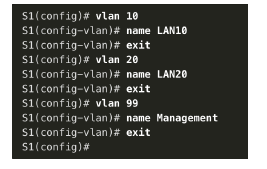
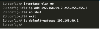
2. Create the management interface. Next, the management interface is created on VLAN 99 along with the default gateway of R1.
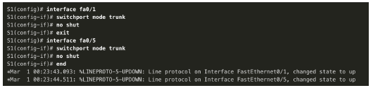
3. Configure access ports. Next, port Fa0/6 connecting to PC1 is configured as an access port in VLAN 10. Assume PC1 has been configured with the correct IP address and default gateway.

4. Configure trunking ports. Finally, ports Fa0/1 connecting to S2 and Fa05 connecting to R1 are configured as trunk ports.
S2 VLAN and Trunking Configuration The configuration for S2 is similar to S1.
R1 Subinterface Configuration The router-on-a-stick method requires you to create a subinterface for each VLAN to be routed. A subinterface is created using the interface interface_id.subinterface_id global configuration mode command. The subinterface syntax is the physical interface followed by a period and a subinterface number. Although not required, it is customary to match the subinterface number with the VLAN number. Each subinterface is then configured with the following two commands: encapsulation dot1q vlan_id - This command configures the subinterface to respond to 802.1Q encapsulated traffic from the specified vlan-id. ip address ip-address subnet-mask - This command configures the IPv4 address of the subinterface. This address typically serves as the default gateway for the identified VLAN. Repeat the process for each VLAN to be routed. Each router subinterface must be assigned an IP address on a unique subnet for routing to occur. When all subinterfaces have been created, enable the physical interface using the no shutdown interface configuration command. If the physical interface is disabled, all subinterfaces are disabled. In the following configuration, the R1 G0/0/1 subinterfaces are configured for VLANs 10, 20, and 99.
Lab 1
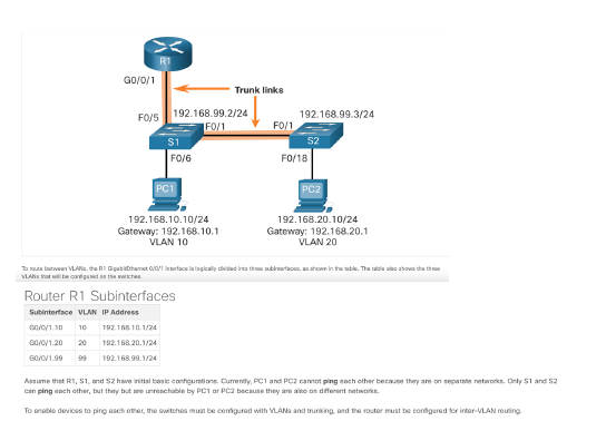
Packet Tracer - Configure Router-on-a-Stick Inter-VLAN Routing In this activity, you will check for connectivity prior to implementing inter-VLAN routing. Then you will configure VLANs and inter-VLAN routing. Finally, you will enable trunking and verify connectivity between VLANs.
R1 GO/0/0 192.168.10.1/24 GO/0/1 192.168.20.1/24 PC1 FO/1 FO/11 FO/12 FO/24 PC2 S1 192.168.10.10/24 VLAN 10 192.168.20.10/24 VLAN 20 Notice in the example MAC address table of S1 is populated as folows: Fa0/1 port is assigned to VLAN 10 and is connected to the R1 G0/0/0 interface. Fa0/11 port is assigned to VLAN 10 and is connected to PC1. Fa0/12 port is assigned to VLAN 20 and is connected to the R1 GO/O/1 interface. Fa0/24 port is assigned to VLAN 20 and is connected to PC2 R1 Surfaces GO/00.10: 172 17.10.1 VLAN 10 G02217217.20.1 VAN 20 GA00.3% 172 17.30.1 IVAN 172.17.10.1724 GOVO/O.10 172.17.30.1/24 GO/0/0.30 FOB F02 Trunk F012 FOM 53 FOM S1 F011 Trunk Trunk Switch S1 Porte PO013 - Trunk Switch 52 Parts F0/11 - VLAN 10 FO/ VLAN 20 10/23 - VLAN 30 PORT Unicast FO2 Ft 52 Fo/11 F0123 F0/18 PCI PC2 PCS 172. 17.1021 172.17.20.22 172. 17.30.23 GO/0/1 Trunk links FO/S 192.168.99.2/24 192.168.99.3/24 FO/1 FO/1 $1 S2 FO/6 FO/18 PC1 PC2 192.168.10.10/24 Gateway: 192.168.10.1 VLAN 10 192.168.20.10/24 Gateway: 192.168.20.1 VLAN 20 Toroute between VLAN, the Al Gabbthet Orface la logically divided into the brows, a shown in the table. The all about the VLA te with Router R1 Subinterfaces Subinterface VLAN IP Address c/0/1.10 10 192.168.10.1/24 20/0y1.20 192.168.20.1/24 GOVOV1.90 99 192.168.99.1/24 Assume that R1, S1, and have initial este conturion Currently, PC1 and PC2 cannot ping each other because they are on separate networks. Only 1 and 52 canping cach other, but they but sinchablety PC or PC because they are on different networks Tonable devices to ping each other, the switches be configured with VLANs and trunking, and the router must be configured for inter VLAN routing R1 GO/0/1 FO/S Trunk links 192.168.99.2/24 192.168.99.3/24 F0/1 F0/1 S1 S2 F0/18 FO/6 PC1 PC2 192.168.10.10/24 Gateway: 192.168.10.1 VLAN 10 192.168.20.10/24 Gateway: 192.168.20.1 VLAN 20 51(config)# vlan 10 si(config-vlan)# name LAN10 51(config-vlan)# exit si(config)# vlan 20 S1(config-vlan)# name LANZO Si(config-vlan)# exit Si(config)# vlan 99 $1(config-vlan)# name Management si(config-vlan)# exit Si(config)# s1(config)# interface vlan 99 Si(config-if)# ip add 192.168.99.2 255.255.255.0 51(config-if)# no shut 51(config-if)# exit 51(config)# ip default-gateway 192.168.99.1 si(config)# 51(config)# interface fab/6 $1(config-if)# switchport node access 51/config-if)# switchport access vlan 10 51/config-if)# no shut si/config-if)# exit si config)# Si config)# interface fa0/1 S1(config-if)# switchport node trunk $1(config-if)# no shut 51(config-if)# exit si(config)# interface fa0/5 sif.config-if)# switchport node trunk Sliconfig-if)# no shut S1(config-if)# end Mar 1 80:23:43.893: SLINEPROTO-5-UPDOWN: Line protocol on Interface FastEthernet0/1, changed state to up Mar i 10:23:44.511: SLINE PROTO-5-UPDOWN: Line protocol on Interface FastEthernet0/5, changed state to up RI GO/0/1 F0/5 Trunk links 192.168.99.2/24 192.168.99.3/24 FO/1 FO/1 S1 FO/6 F0/18 PC1 192.168.10.10/24 192.168.20.10/24 Gateway: 192.168.10.1 Gateway: 192.168.20.1 VLAN 10 VLAN 20 52(config)a vlan 10 52(config-vlan)# nane LANIB 52(config-vlan)# exit S2(config)# vlan 20 S2(config-vlan)# nane LAN20 S2(config-vlan)* exit 52(contagia vlan 99 S2(config-vlan)# nane Managenent S2(config-vlan) exit S2(config)# 52(config)# interface vlan 99 52(config-if)# ip add 192.168.99.3 255.255.255.0 52(config-if)# no shut S2(config-if)# exit S2(config)# ip default-gateway 192.168.99.1 S2(config)# interface fab/18 52(config-if)# switchport mode access 52(config-if)# switchport access vlan 20 S2(config-if)# no shut S2(config-if)# exit 52(config)a interface fab/1 52(config-if)# switchport mode trunk 52(config-if)# no shut S2(config-if)# exit S2(config-if)# end *Mar 1 08:23:52.137: SLINEPROTO-5-UPDOWN: Line protocol on Interface FastEthernete/1, changed state to up > R1 G0/0/1 Trunk links F0/5 192.168.99.2/24 192.168.99.3/24 FO/1 FO/1 S1 S2 FO/6 F0/18 PC1 PC2 192.168.10.10/24 Gateway: 192.168.10.1 VLAN 10 192.168.20.10/24 Gateway: 192.168.20.1 VLAN 20 R1(config)# interface GB/0/1.10 R1(config-subifla description Default Gateway for VLAN 10 Riconfig-sublf# encapsulation dot10 10 R1(config-subifla ip add 192.168.10.1 255.255.255.0 R1(config-subifla exit Rlconfig)# R1(config)# interface GB/0/1.20 Racconfig-subifla description Default Gateway for VLAN 20 Rlconfig-subif)# encapsulation dot1Q 20 Ri(config-subifis ip add 192.168.20.1 255.255.255.0 R1(config-subif) exit Rlconfig)# R1(config)# interface Go/8/1.99 Riconfig-subif)# description Default Gateway for VLAN 99 R1(config-subif)# encapsulation dot1Q 99 Ri(config-subiflip add 192.168.99.1 255.255.255.0 Riconfig-subifis exit Rl contige Riconfig)# interface G8/0/1 R1(config-if)# description Trunk link to si Rlconfig-ifle no shut Riconfi9-10). and Ria *Sep 15 19:08:47.815: SLINK-3-UPDOWN: Interface GigabitEthernete/e/1, changed state to down +Sep 15 19:88:58.071: LINK-3-UPDOWN: Interface GigabitEthernet/0/1, changed state to up *Sep 15 19:88:51.871: SLINEPROTO-5-UPDOWN: Line protocol on Interface GigabitEthernet0/0/1, changed state to up R14
Step by Step Solution
There are 3 Steps involved in it

Get step-by-step solutions from verified subject matter experts