

Question: Lab Task 4: Configure R1 for Inter-VLAN Roliting Configure the router on the Office 1 network to allow multiple VLANs to communicate on the network.
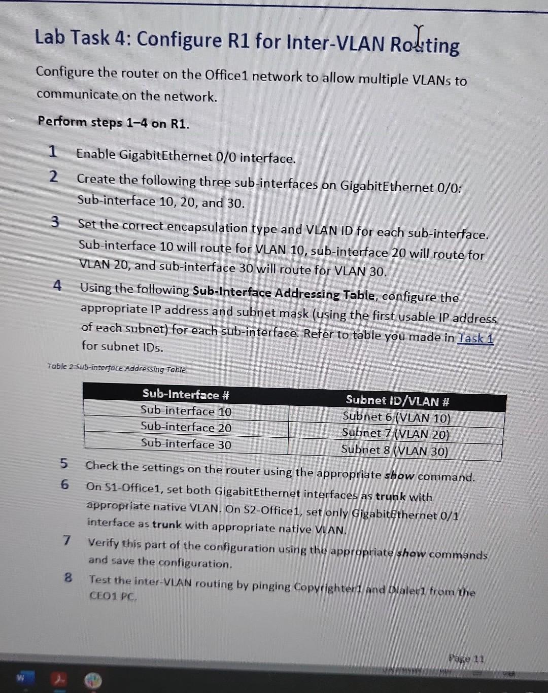
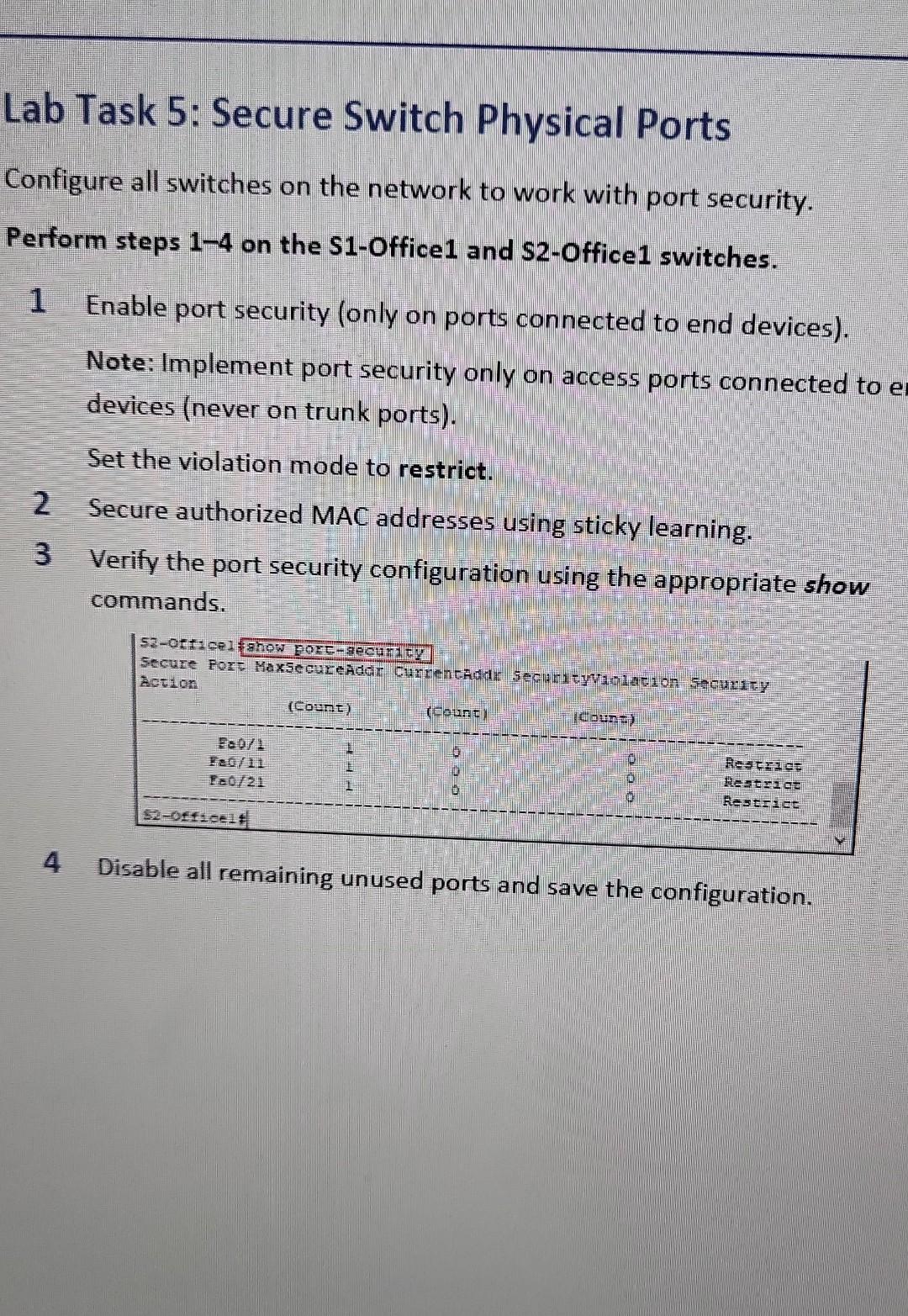
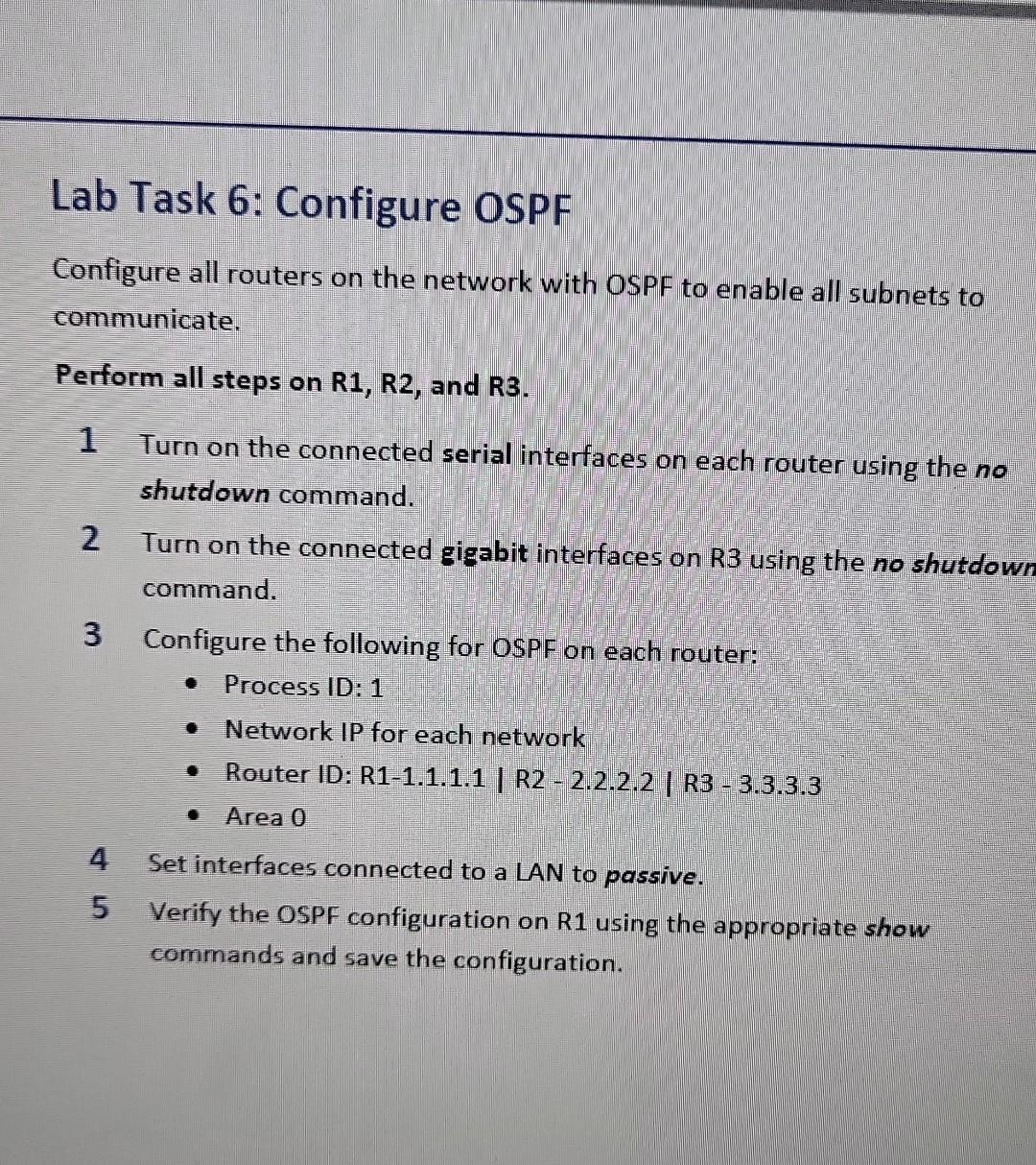
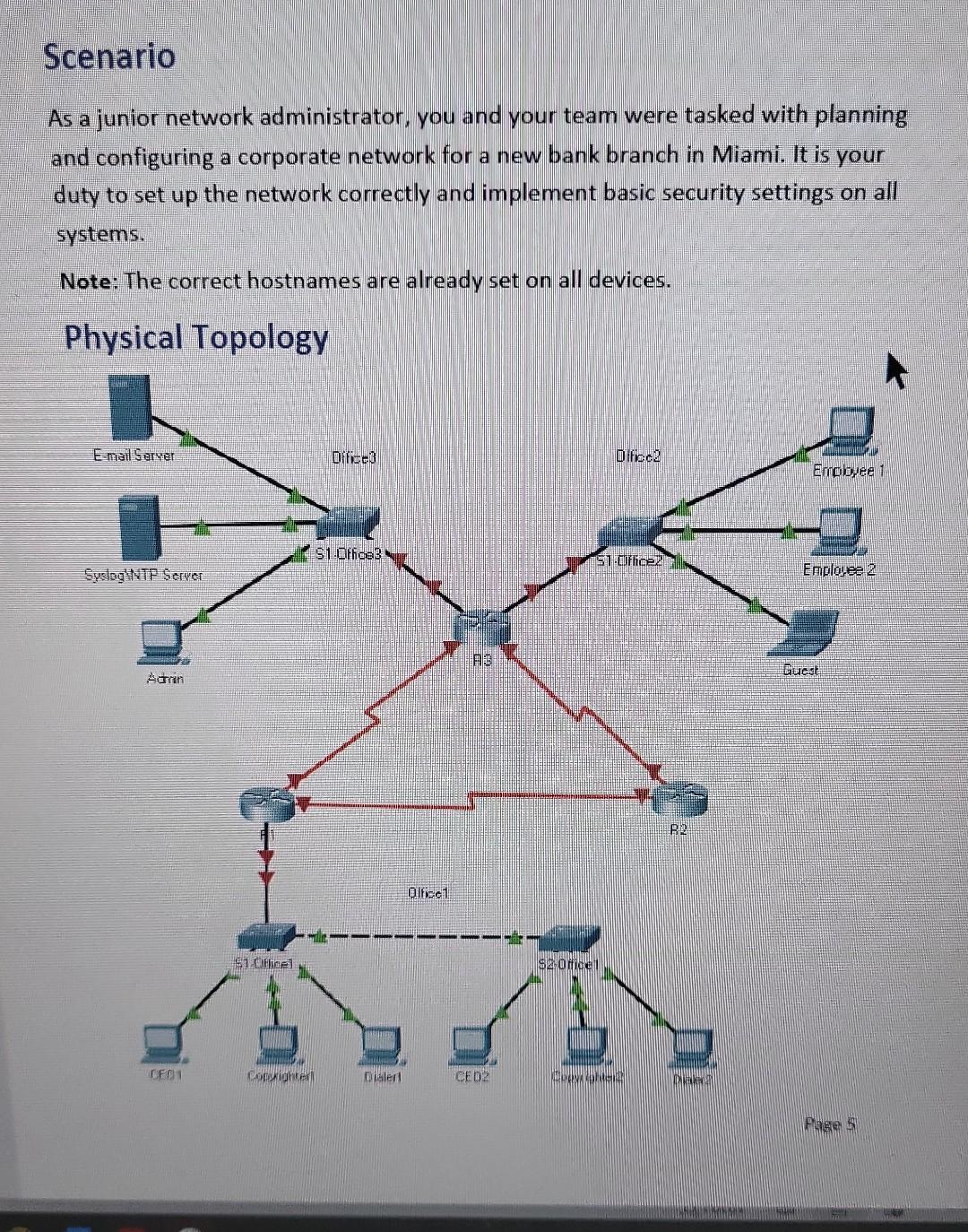
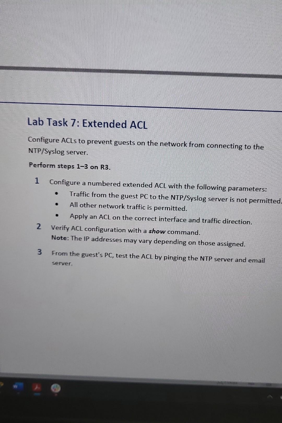
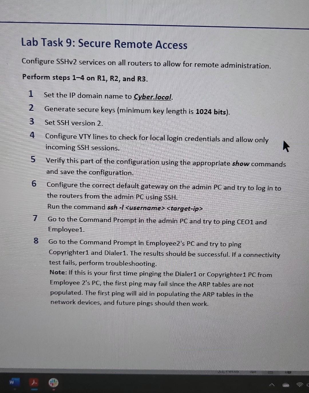
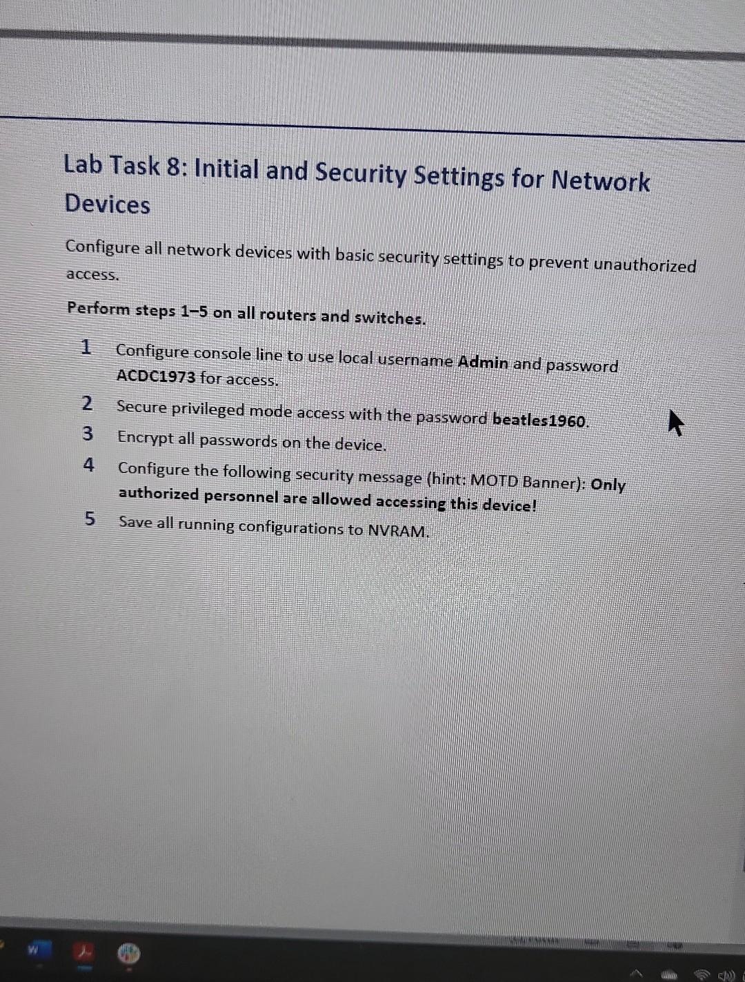
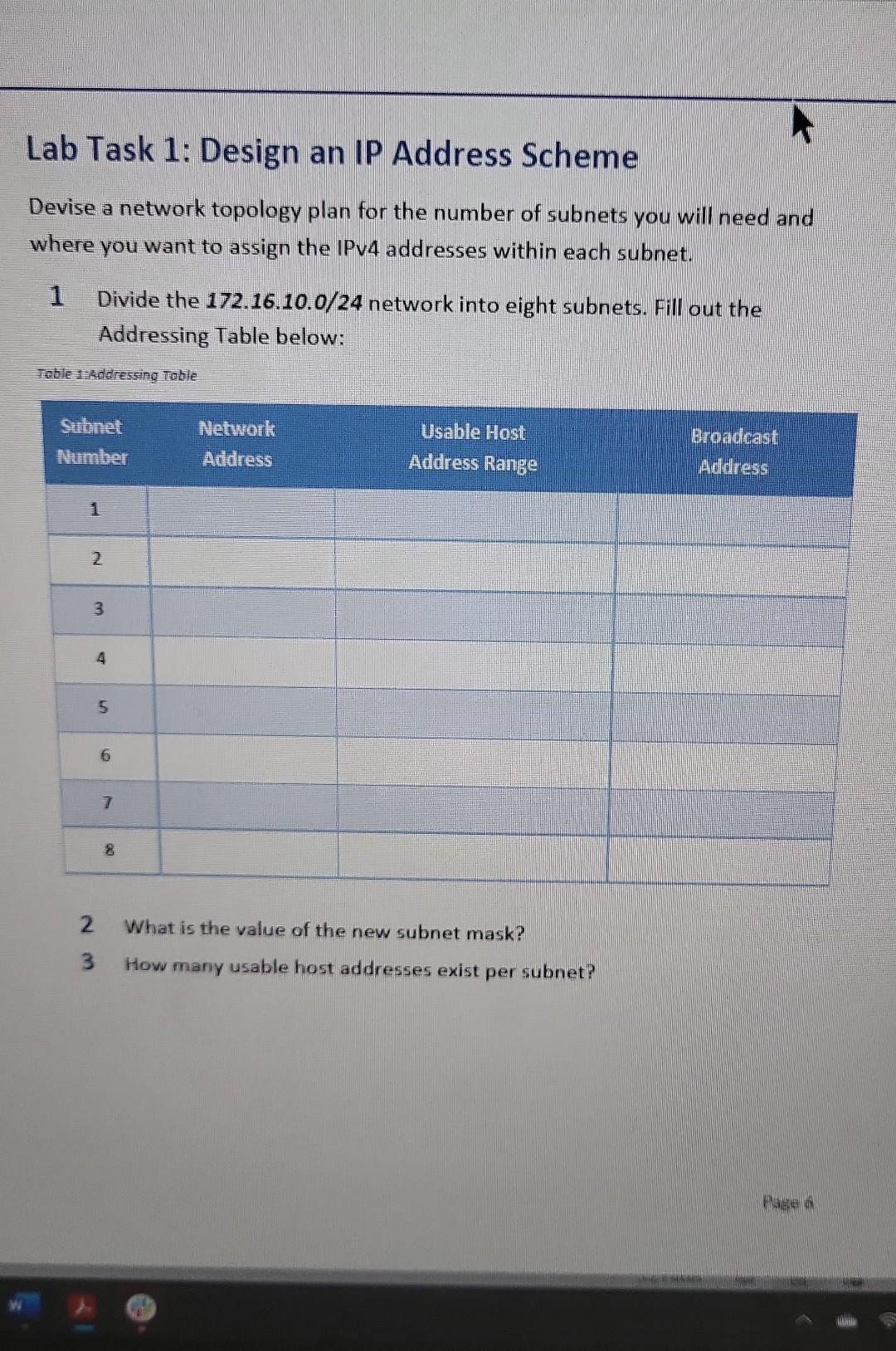
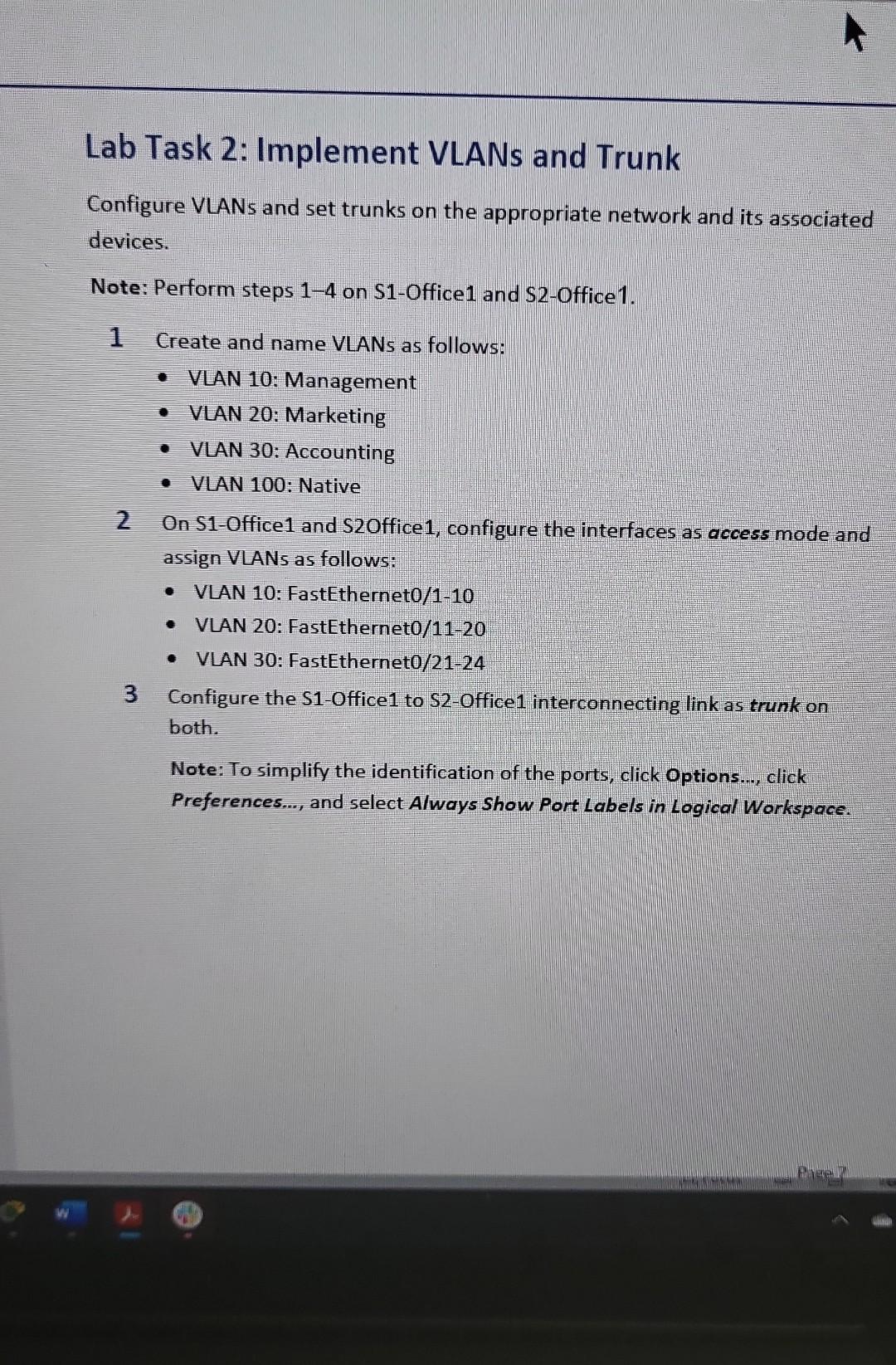
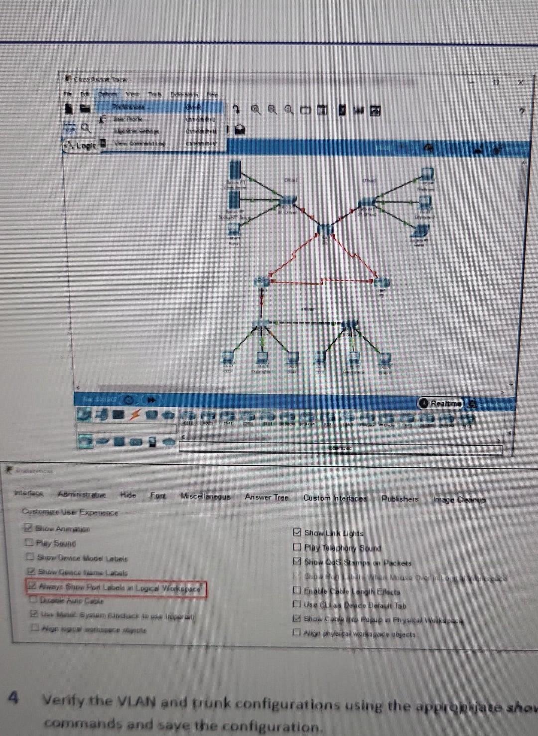
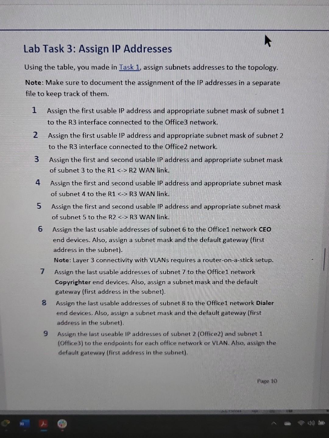
Lab Task 4: Configure R1 for Inter-VLAN Roliting Configure the router on the Office 1 network to allow multiple VLANs to communicate on the network. Perform steps 14 on R1. 1 Enable GigabitEthernet 0/0 interface. 2 Create the following three sub-interfaces on GigabitEthernet 0/0: Sub-interface 10,20 , and 30 . 3 Set the correct encapsulation type and VLAN ID for each sub-interface. Sub-interface 10 will route for VLAN 10 , sub-interface 20 will route for VLAN 20, and sub-interface 30 will route for VLAN 30. 4 Using the following Sub-Interface Addressing Table, configure the appropriate IP address and subnet mask (using the first usable IP address of each subnet) for each sub-interface. Refer to table you made in Task1 for subnet IDs. Toble 2.5ub-interface Addressing Table 5 Check the settings on the router using the appropriate show command. 6 On S1-Office 1, set both GigabitEthernet interfaces as trunk with appropriate native VLAN. On S2-Office1, set only GigabitEthernet 0/1 interface as trunk with appropriate native VLAN. 7 Verify this part of the configuration using the appropriate show commands and save the configuration. 8 Test the inter-VLAN routing by pinging Copyrighter1 and Dialer1 from the CEO1 PC. Lab Task 5: Secure Switch Physical Ports Configure all switches on the network to work with port security. Perform steps 1-4 on the S1-Office1 and S2-Office1 switches. 1 Enable port security (only on ports connected to end devices). Note: Implement port security devices (never on trunk ports). Set the violation mode to restrict. 2 Secure authorized MAC addresses using sticky learning. 3 Verify the port security configuration using the appropriate show commands. 4 Disable all remaining unused ports and save the configuration. Configure all routers on the network with OSPF to enable all subnets to communicate. Perform all steps on R1,R2, and R3. 1 Turn on the connected serial interfaces on each router using the no shutdown command. 2 Turn on the connected gigabit interfaces on R3 using the no shutdowi command. 3 Configure the following for OSPF on each router: - Process ID: 1 - Network IP for each network - Router ID: R1-1.1.1.1 | R2 - 2.2.2.2 | R3 - 3.3.3.3 - Area 0 4 Set interfaces connected to a LAN to passive. 5 Verify the OSPF configuration on R1 using the appropriate show commands and save the configuration. Scenario As a junior network administrator, you and your team were tasked with planning and configuring a corporate network for a new bank branch in Miami. It is your duty to set up the network correctly and implement basic security settings on all systems. Note: The correct hostnames are already set on all devices. Lab Task 7: Extended ACL Configure ACLs to prevent guests on the network from connecting to the NTP/Syslog server. Perform steps 1-3 on R3. 1 Configure a numbered extended ACL with the following parameters: - Traffic from the guest PC to the NTP/Syslog server is not permitted - All other network traffic is permitted. - Apply an ACL on the correct interface and traffic direction. 2 Verify ACL configuration with a show command. Note: The IP addresses may vary depending on those assigned. 3 From the guest's PC, test the ACL by pinging the NTP server and email server. Lab I ask 9: secure Remote Access Configure SSHv2 services on all routers to allow for remote administration. Perform steps 14 on R1,R2, and R3. 1 Set the IP domain name to Cyber.local. 2 Generate secure keys (minimum key length is 1024 bits). 3 SetSSH version 2. 4 Configure VTY lines to check for local login credentials and allow only incoming SSH sessions. 5 Verify this part of the configuration using the appropriate show commands and save the configuration. 6 Configure the correct default gateway on the admin PC and try to log in to the routers from the admin PC using SSH. 7 Go to the Command Prompt in the admin PC and try to ping CEO1 and Employee1. 8 Go to the Command Prompt in Employee2's PC and try to ping Copyrighter 1 and Dialer 1 . The results should be successful. If a connectivity test fails, perform troubleshooting. Note: If this is your first time pinging the Dialer1 or Copyrighter1 PC from Employee 2's PC, the first ping may fail since the ARP tables are not populated. The first ping will aid in populating the ARP tables in the network devices, and future pings should then work. Lab Task 8: Initial and Security Settings for Network Devices Configure all network devices with basic security settings to prevent unauthorized access. Perform steps 15 on all routers and switches. 1 Configure console line to use local username Admin and password ACDC1973 for access. 2 Secure privileged mode access with the password beatles 1960. 3 Encrypt all passwords on the device. 4 Configure the following security message (hint: MOTD Banner): Only authorized personnel are allowed accessing this device! 5 Save all running configurations to NVRAM. Lab Task 1: Design an IP Address Scheme Devise a network topology plan for the number of subnets you will need and where you want to assign the IPv4 addresses within each subnet. 1 Divide the 172.16.10.0/24 network into eight subnets. Fill out the Addressing Table below: Toble tidadressing Toble 2 What is the value of the new subnet mask? 3 How many usable host addresses exist per subnet? Lab Task 2: Implement VLANs and Trunk Configure VLANs and set trunks on the appropriate network and its associated devices. Note: Perform steps 14 on S1-Office 1 and S2-Office 1. 1 Create and name VLANs as follows: - VLAN 10: Management - VLAN 20: Marketing - VLAN 30: Accounting - VLAN 100: Native 2 On S1-Office1 and S2Office1, configure the interfaces as access mode and assign VLANs as follows: - VLAN 10: FastEthernet0/1-10 - VLAN 20: FastEthernet0/11-20 - VLAN 30: FastEthernet0/21-24 3 Configure the S1-Office1 to S2-Office1 interconnecting link as trunk on both. Note: To simplify the identification of the ports, click Options..., click Preferences..., and select Always Show Port Labels in Logical Workspace. 4 Verify the VIAN and trunk configurations using the appropriate show commands and save the configuration. Using the table, you made in Iask 1, assign subnets addresses to the topology. Note: Make sure to document the assignment of the IP addresses in a separate file to keep track of them. 1 Assign the first usable IP address and appropriate subnet mask of subnet 1 to the R3 interface connected to the Office3 network. 2 Assign the first usable IP address and appropriate subnet mask of subnet 2 to the R3 interface connected to the Office2 network. 3 Assign the first and second usable IP address and appropriate subnet mask of subnet 3 to the R1
Step by Step Solution
There are 3 Steps involved in it

Get step-by-step solutions from verified subject matter experts