

Question: Melbourne undergoes frequent droughts with below - annual - average rainfall. Record low inflows to water reservoirs and a growing urban population mean new water
Melbourne undergoes frequent droughts with belowannualaverage rainfall. Record low inflows to water
reservoirs and a growing urban population mean new water sources for Melbourne need to be found. The
Victorian Government's 'Our Water Our Future' outlines major infrastructure projects to secure Victoria's water
supplies in the face of drought and the challenge of climate change. One of these projects has built a pipeline
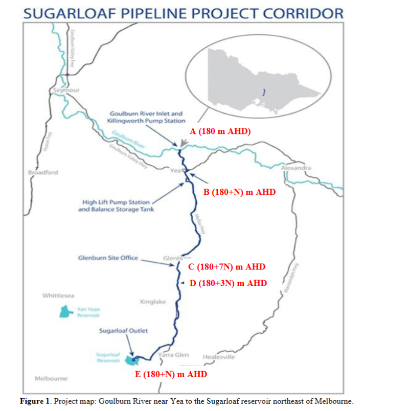
connecting the Goulburn River near Yea to the Sugarloaf reservoir northeast of Melbourne Figure The
Sugarloaf pipeline will transfer up to gigalitres GL of water annually to Melbourne. More information on
the Sugarloaf pipeline project can be obtained from wwwsugarloafpipeline.com.au
As shown in Figure water will be pumped with two parallel pump systems from the Goulburn River at Point
A near Killingworth assume river water level elevation is m AHD to two parallel storage tanks km
away at Point B Each tank would have hours flow retaining capacity at a maximum water level of N m
AHD N has been defined later From these tanks, water will again be pumped to an elevation of N m
AHD at Point C by two parallel pipe and pump systems, where each parallel system will have a few pumps in
series connection number of pumps needs to be found out to convey water over the Great Dividing Range
along the Melba Highway. The distance from Point B to Point C is L km When selecting the pumps, you need
to ensure that the pressure at Point C is not cavitational ie it's a phenomenon where negative pressure
develops below the vapor pressure to create noise vibration and thus disrupts the flow From Point C to Point D
at Kinglake, water is transferred through a single pipe called penstock to an elevation of N m AHD at
m away. This flow will rotate a hydraulic turbine, driving a generator to produce and supply electrical
power to the area. The water from the turbine will move to a downstream artificial reservoir of size enough to
hold days flow. The area available for the reservoir construction is a maximum of ha
From point D downward, water will flow under gravity through an existing Ltimes L km long and mm
diameter cast iron pipeline up to the Sugarloaf reservoir at point E There is a possibility that the existing
mm diameter pipeline is not enough to carry the required design flow. So to increase the flow capacity of the
system, it may require joining a parallel pipeline to the existing pipeline between points D and E As such, a new
pipeline may be joined between times L km and times L km to form a looped parallel pipeline system. It means
the existing pipeline will remain single for lengths of times L km at the beginning at point D and then times L
km at the end at point E You need to find the diameter for the new parallel pipeline to see that the increased
flow capacity and the existing pipeline flow are equal or marginally more than the design flow. As shown in the
figure, points D and E have an elevation difference of about Ntimes m
The assignment aims to design the water pipeline for the above water transfer system from the Goulburn River
to the Sugarloaf reservoir to carry approximately GL of water annually to Melbourne. Note that I have
reduced the discharge due to the high head required in the pump to discharge GL of water Assume sufficient water to pump from the Goulburn River after allowing environmental flows. Determine the
pipe sizes, holding tank size at point B manmade reservoir size at point D and its bottom elevation, the energy
required to pump water up to the Great Dividing Range, and the energy generated from the turbine when water
is transferred to Kinglake at Point D and then the size of the new parallel pipeline along the existing pipeline up
to Sugarloaf Outlet at Point E
Step Sketch the pipeline layout connecting the Goulburn River to the power station in Kinglake and then up
to Sugarloaf Outlet. Assume that the water is flowing at a steadystate condition.
Step Assume a diameter for each parallel pipeline between A and B and the pipe's material. Use the Moody
diagram to determine the frictional loss in pipes and include all minor losses eg entrance, valve, exit, etc
Write the energy eq to obtain the System eq in head lost corresponding to a discharge. Superimpose the System
eq curve onto the Pump characteristic curves to select an Operating point where discharge is equal or slightly
higher than the required discharge. Read the corresponding size of the pump, its head, and the power required
with pump efficiency. If the obtained discharge is deemed unsatisfactory, another pipe size can be assumed until
a sufficient pumping head is achieved to deliver the required flow to the holding tank at B Estimate the holding
tanks size for the flow rate and the given hours of operation.
Pump characteristic curves can be obtained on L VALUE: KM N VALUE: M KM DISCHARGE QGLYR LS COMPLETE STEP AND REPORT FORMAT calculations introducton and objective, selection of pipes, procedure of selecting the pump, rationale behind selecting the maximum discharge, justifications for all assumptions used.
Step by Step Solution
There are 3 Steps involved in it
1 Expert Approved Answer
Step: 1 Unlock

Question Has Been Solved by an Expert!
Get step-by-step solutions from verified subject matter experts
Step: 2 Unlock
Step: 3 Unlock