

Question: Mini Project Networking-II (Routing and Switching Essentials) Introduction In this practice skills assessment, you will configure the Sohar University network. You will perform basic router
Mini Project
Networking-II (Routing and Switching Essentials)
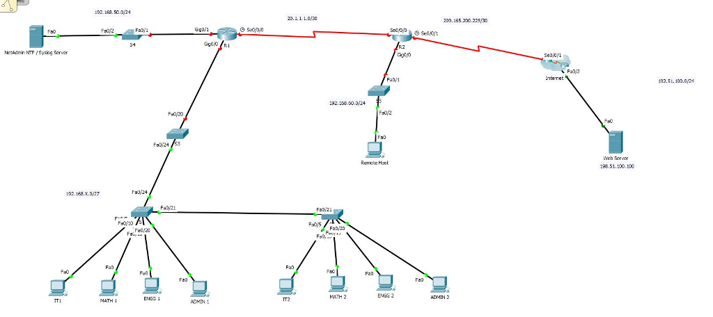
Introduction In this practice skills assessment, you will configure the Sohar University network. You will perform basic router configuration tasks, address router interfaces and hosts, and configure VLANs, trunking, and routing between VLANs and DHCP. You will also configure and customize RIPv2 and control access to router vty lines with a standard named ACL. For a full list of tasks, see below.
Addressing Table:
| Device | Interface | Network | Comments |
| R1 | S0/0/0 | 20.1.1.0/30 | any address in the network |
| G0/0.10 | 192.168.X.0/27 | First subnet / first address in the network | |
| G0/0.20 | 192.168.X.0/27 | Second Subnet / first address in the network | |
| G0/0.30 | 192.168.X.0/27 | Third subnet / first address in the network | |
| G0/0.99 | 192.168.X.0/27 | Fourth subnet / first address in the network | |
| G0/1 | 192.168.50.0/24 | first address in the network | |
| R2 | S0/0/0 | 20.1.1.0/30 | any address in the network |
| S0/0/1 | 209.165.200.0/28 | First address in the network | |
| G0/0 | 192.168.60.0/24 | first address in the network | |
| S1 | SVI | 192.168.X.0/24 | Second address in the network |
| S2 | SVI | 192.168.X.0/24 | Third address in the network |
| S3 | SVI | 192.168.X.0/24 | Fourth address in the network |
| NetAdmin (NTP / Syslog) | Fa0/0 | 192.168.50.0/24 | Last address in the network |
| Remote Host | Fa0/0 | 192.168.60.0/24 | Fifth address in the network |
Where X= Last digit of student ID.
VLAN Table:
| VLAN Number | VLAN Name | VLAN Network | Device: Port |
| 10 | IT | 192.168.X.0/27 First subnet in the network | S1: Fa0/5 S2: Fa0/5 |
| 20 | Elc | 192.168.X.0/27 Second subnet in the network | S1: Fa0/10 S2: Fa0/10 |
| 30 | Engg | 192.168.X.0/27 Third subnet in the network | S1: Fa0/15 S2: Fa0/15 |
| 99 | Admin&Management | 192.168.X.0/27 Fourth subnet in the network | S1: Fa0/20 SVI S2: Fa0/20, SVI |
Instructions All IOS device configurations should be completed from a direct terminal connection to the device console. In addition, many values that are required to complete the configurations have not been given to you. In those cases, create the values that you need to complete the requirements.
You will practice and be assessed on the following skills:
Configuration of initial device settings
Interface addressing
Configuration of VLANs and trunking
Routing between VLANs
Dynamic routing with RIPv2
Configuration of standard ACLs
Switch port security configuration
Remote switch management configuration
Syslog and NTP configuration
Step1: Basic Device Configuration
Complete a basic device configuration on the R1 router. Perform the following tasks:
Disable DNS lookup.
Configure the device with the name shown in the addressing table.
Configure password encryption.
Assign the encrypted type of privileged EXEC password.
Configure a MOTD banner to warn users that unauthorized access is prohibited.
Configure the console line so that router status messages will not interrupt command line input.
Configure the console to require a password for access. (Give your name)
Configure the VTY ports to only accept connections over SSH. Use the following values:
| Domain Name | cisco.com |
| Local Username: | admin |
| User Password: | class |
| Modulus: | 1024 |
| Version: | 2 |
The values for your SSH configuration must match these values exactly in order for you to receive credit for your configuration.
Step 2: Interface Addressing Router R1
Activate and configure the G0/1 and S0/0/0 interfaces of the R1 router with the IP addresses given in the Addressing Table.
NOTE: The G0/0 interface will be configured later in the assessment.
Step 3: VLANs and Trunking
Configure the S1, S2, and S3 switches with VLANs and trunking according to the values in the VLAN table.
Add the VLANs to the switches.
Name the VLANs exactly as shown in the VLAN table.
Assign the appropriate ports to the VLANs.
Configure appropriate interfaces as trunks
Step 4: Routing Between VLANs (Inter vlan Sub interfaces)
Configure routing between VLANs on the R1 router. Use the information in the addressing and VLAN tables.
Step 5: Switch Virtual Interface (SVI) Configuration
Configure the switch virtual management interfaces on S1, S2, and S3. Use the information in the addressing and VLAN tables for your configuration. All switches should be reachable from hosts on other networks for the purpose of this assessment.
Step 6: Switch Port Security Configuration
Improve network security by configuring the S1 switch with the following. You are only required to configure these settings on this one switch for this assessment.
Disable ALL unused switch ports.
Activate port security on all ports that have hosts connected.
Allow only a maximum of Four MAC addresses to access the active switch ports.
Configure the switch ports to automatically learn the two allowed MAC addresses and record the addresses in the running configuration.
Configure the switch ports so that, if the maximum number of addresses for each port is exceeded, packets with unknown source addresses are dropped until a sufficient number of secure MAC addresses are removed. Notification that a violation has occurred is not required.
Step 7: Interface Addressing and static route on Router R2
Activate and configure the S0/0/0 and S0/0/1 interfaces of the R2 router with the IP addresses given in the Addressing Table.
Configure Default static route on exit interface of R2, So that all the users can access the internet.
NOTE: The G0/0 interface will be configured later in the assessment.
Step 8: Dynamic Routing
Configure RIPv2 routing on R1 and R2.
Configure RIPv2 on R1 and R2 so that all networks are reachable.
Configure all LAN physical interfaces so that RIP updates are not sent out to the LANs.
Be sure to use the version of RIP that supports classless routing.
Prevent RIP from automatically summarizing networks.
Configure RIP to automatically send the default route that is already configured on R2 to R1.
Step 9: Configure DHCP R1 router should be configured as a DHCP server that provides addressing to the hosts attached to S1 and S2. The requirements are as follows:
Use VLAN10, VLAN 20, VLAN 30 and VLAN 99 as the pool names. Note that the pool names must match the names given here exactly, all capital letters and exact spelling.
Addresses .1 to .10 should be reserved for static assignment from each pool.
The first address in each network will be assigned to the router interface attached to the networks as shown in the addressing table.
Ensure that hosts in each LAN are able to communicate with hosts on remote networks.
Step 10: Access Control List Configuration
Configure a named standard ACL that meets the following requirements:
The list should be named block15. The name must match this value exactly in order for you to receive credit for your work.
Prevent any host with an address on the VLAN15 sub network from accessing the VLAN10 sub network.
All other hosts should be permitted
The list should have two statements.
Step 11: Configure Host Addressing
Assign IP addresses for Remote host, NTP/Syslog Server and Web server from the Addressing Table.
Step 12: Configure Network Monitoring
Configure NTP and Syslog server logging on R1.
Activate the logging and debug timestamp services.
Configure R1 as an NTP client. The NTP/Syslog server with the last address of 192.168.50.0/24.
Configure Syslog to send debug level messages to the NTP/Syslog logging server.
Step 13: Configure Static NAT
Configure NAT to translate internal private addresses into public addresses for the Internet. The requirements are:
a. Configure static NAT to the Remote host.
Translate the internal address of the remote host to the address 209.165.200.10.
Configure the correct interfaces to perform this NAT translation.
Submit the packet tracer File.
192.168.50.021 20.1.11.0/30 20.155.200.22530 GgDll Nodmin NT Sysiog Seruer Fad 1 92.5.100.0/21 :92.188.00.0/24 Remobe Host 198.51.100100 102.168.x.077 Fa0/21 FaD 21 Fel/20 Four FaD, FaD MATH 2 ENGG 2 ADMIN 2 MATH 1 ENGS 1 ADMTN IT2 192.168.50.021 20.1.11.0/30 20.155.200.22530 GgDll Nodmin NT Sysiog Seruer Fad 1 92.5.100.0/21 :92.188.00.0/24 Remobe Host 198.51.100100 102.168.x.077 Fa0/21 FaD 21 Fel/20 Four FaD, FaD MATH 2 ENGG 2 ADMIN 2 MATH 1 ENGS 1 ADMTN IT2
Step by Step Solution
There are 3 Steps involved in it

Get step-by-step solutions from verified subject matter experts