

Question: // Module that connects ten switches and lights module part1 (SW. LEDR): input [9:01 SW; // slide switches output 19:01 LEDR; // red LEDs assign
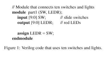
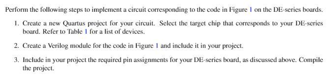
// Module that connects ten switches and lights module part1 (SW. LEDR): input [9:01 SW; // slide switches output 19:01 LEDR; // red LEDs assign LEDR = SW; endmodule Figure 1: Verilog code that uses ten switches and lights. Perform the following steps to implement a circuit corresponding to the code in Figure 1 on the DE-series boards. 1. Create a new Quartus project for your circuit. Select the target chip that corresponds to your DE-series board. Refer to Table 1 for a list of devices. 2. Create a Verilog module for the code in Figure 1 and include it in your project. 3. Include in your project the required pin assignments for your DE-series board, as discussed above. Compile the project. // Module that connects ten switches and lights module part1 (SW. LEDR): input [9:01 SW; // slide switches output 19:01 LEDR; // red LEDs assign LEDR = SW; endmodule Figure 1: Verilog code that uses ten switches and lights. Perform the following steps to implement a circuit corresponding to the code in Figure 1 on the DE-series boards. 1. Create a new Quartus project for your circuit. Select the target chip that corresponds to your DE-series board. Refer to Table 1 for a list of devices. 2. Create a Verilog module for the code in Figure 1 and include it in your project. 3. Include in your project the required pin assignments for your DE-series board, as discussed above. Compile the project
Step by Step Solution
There are 3 Steps involved in it

Get step-by-step solutions from verified subject matter experts