

Question: Multisim Help please! I am trying to build a simple crystal oscillator in multisim that produces a sinewave, but i'm having difficultly doing it. Can
Multisim Help please!
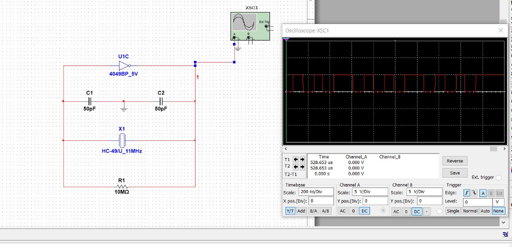
I am trying to build a simple crystal oscillator in multisim that produces a sinewave, but i'm having difficultly doing it. Can someone please help. I will post a snapshot of what I have done but I don't know for certain that the components are right. Thank You.
note: I don't know how to add the +VCC and -VCC to the CMOS inverter and I'm not sure if i'm using the right CMOS. Also, I keep getting squarewave instead of sinewave.
Thanks again!!!
Instructions:
My Work:
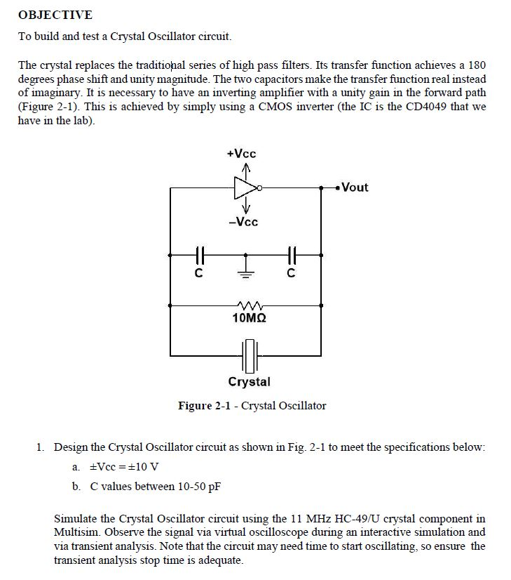
OBJECTIVE To build and test a Crystal Oscillator circuit. The crystal replaces the traditiohal series of high pass filters. Its transfer function achieves a 180 degrees phase shift and unity magnitude. The two capacitors make the transfer function real instead of imaginary. It is necessary to have an inverting amplifier with a unity gain in the forward path (Figure 2-1). This is achieved by simply using a CMOS inverter (the IC is the CD4049 that we have in the lab). +Vcc tVout Vcc 10 Crystal Figure 2-1 - Crystal Oscillator 1. Design the Crystal Oscillator circuit as shown in Fig. 2-1 to meet the specifications below: Vcc = 10 V b. C values between 10-50 pF Simulate the Crystal Oscillator circuit using the 11 MHz HC-49/U crystal component in Multisim. Observe the signal via virtual oscilloscope during an interactive simulation and via transient analysis. Note that the circuit may need time to start oscillating, so ensure the transient analysis stop time is adequate OBJECTIVE To build and test a Crystal Oscillator circuit. The crystal replaces the traditiohal series of high pass filters. Its transfer function achieves a 180 degrees phase shift and unity magnitude. The two capacitors make the transfer function real instead of imaginary. It is necessary to have an inverting amplifier with a unity gain in the forward path (Figure 2-1). This is achieved by simply using a CMOS inverter (the IC is the CD4049 that we have in the lab). +Vcc tVout Vcc 10 Crystal Figure 2-1 - Crystal Oscillator 1. Design the Crystal Oscillator circuit as shown in Fig. 2-1 to meet the specifications below: Vcc = 10 V b. C values between 10-50 pF Simulate the Crystal Oscillator circuit using the 11 MHz HC-49/U crystal component in Multisim. Observe the signal via virtual oscilloscope during an interactive simulation and via transient analysis. Note that the circuit may need time to start oscillating, so ensure the transient analysis stop time is adequate
Step by Step Solution
There are 3 Steps involved in it

Get step-by-step solutions from verified subject matter experts