

Question: Need help. Design and simulate a 4-Bit ALU that performs following operations, Operation Output/Description Addition Output C=A+B Status I = Carry out Status2 = Overflow
Need help.
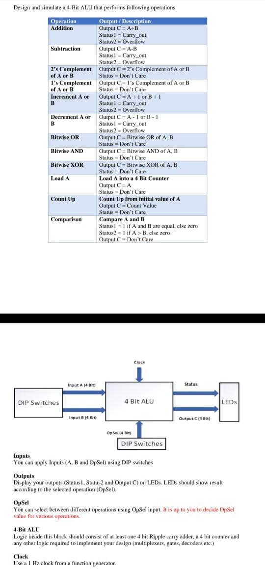
Design and simulate a 4-Bit ALU that performs following operations, Operation Output/Description Addition Output C=A+B Status I = Carry out Status2 = Overflow Subtraction Output C=A-B Status] = Carry_out Status2 = Overflow 2's Complement Output C=2's Complement of A or B of A or B Status - Don't Care I's Complement Output C = 1's Complement of A or B of A or B Status Don't Care Increment A or Output C = A + 1 or B + 1 B Status1 = Carry out Status2 = Overflow Decrement A or Output C=A-or B-1 B Status] = Carry out Status2 = Overflow Bitwise OR Output C = Bitwise OR of A, B Status =Don't Care Bitwise AND Output C = Bitwise AND of A, B Status Don't Care Bitwise XOR Output C = Bitwise XOR of A. B Status Don't Care Load A Load A into a 4 Bit Counter Output C=A Status - Don't Care Count Up Count Up from initial value of A Output C = Count Value Status Don't Care Comparison Compare A and B Status= 1 if A and B are equal, else zero Status2 - 1 if A>B, else zero Output C=Don't Care Clock Input A 4 DIE () Status DIP Switches 4 Bit ALU LEDs Input (4 bit) Output C (451) Opset (4 bit) DIP Switches Inputs You can apply Inputs (A, B and OpSel) using DIP switches Outputs Display your outputs (Status 1. Status 2 and Output C) on LEDs. LEDs should show result according to the selected operation (OpSel). OpSel You can select between different operations using Opel input. It is up to you to decide OpSel value for various operations 4-Bit ALU Logic inside this block should consist of at least one 4 bit Ripple carry adder, a 4 bit counter and any other logic required to implement your design (multiplexers, gates, decoders etc.) Clock Use a 1 Hz clock from a function generator
Step by Step Solution
There are 3 Steps involved in it

Get step-by-step solutions from verified subject matter experts