

Question: Need help writing/implementing code for this lab in VHDL Start with the controller We are going to start with the controller Create VHDL code to
Need help writing/implementing code for this lab in VHDL
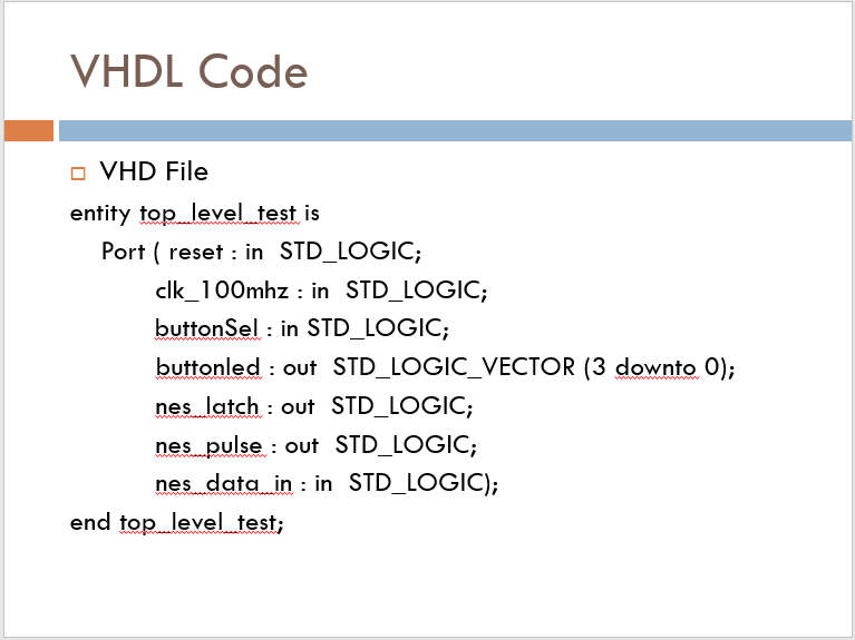
Start with the controller We are going to start with the controller Create VHDL code to generate the signals and read the buttons press Could be done by bit-banging on the CPU but we have the resources for all the timing to be done outside of the CPU Later we will connect our hardware to the CPU VHDL Code VHD File entity top level test is Port ( reset : in STD_LOGIC; clk_100mhz : in STD_LOGIC; buttonSel : in STD_LOGIC; buttonled : out STD_LOGIC_VECTOR (3 downto 0); nes latch : out STD_LOGIC; nes pulse : out STD_LOGIC; nes data in : in STD_LOGIC); end top level test; Example Output: You will use the 4 LEDs to display the buttons You will also use 1 dip switch. The dip switch will select which buttons are shown on the LEDs. We have 8 buttons and 4 LEDs You will need to interface the joystick to the board Start with the controller We are going to start with the controller Create VHDL code to generate the signals and read the buttons press Could be done by bit-banging on the CPU but we have the resources for all the timing to be done outside of the CPU Later we will connect our hardware to the CPU VHDL Code VHD File entity top level test is Port ( reset : in STD_LOGIC; clk_100mhz : in STD_LOGIC; buttonSel : in STD_LOGIC; buttonled : out STD_LOGIC_VECTOR (3 downto 0); nes latch : out STD_LOGIC; nes pulse : out STD_LOGIC; nes data in : in STD_LOGIC); end top level test; Example Output: You will use the 4 LEDs to display the buttons You will also use 1 dip switch. The dip switch will select which buttons are shown on the LEDs. We have 8 buttons and 4 LEDs You will need to interface the joystick to the board
Step by Step Solution
There are 3 Steps involved in it

Get step-by-step solutions from verified subject matter experts