

Question: ****************************************** VHD STRUCTURAL CODE *************************************************** Library IEEE; use IEEE.STD_LOGIC_1164.all; use IEEE.STD_LOGIC_MISC.all; use IEEE.STD_LOGIC_ARITH.all; ----------------integer register-------------------- Library IEEE; use IEEE.std_logic_1164.all; use IEEE.std_logic_misc.all; use IEEE.std_logic_arith.all; Entity Reg
****************************************** VHD STRUCTURAL CODE ***************************************************
Library IEEE; use IEEE.STD_LOGIC_1164.all; use IEEE.STD_LOGIC_MISC.all; use IEEE.STD_LOGIC_ARITH.all; ----------------integer register-------------------- Library IEEE; use IEEE.std_logic_1164.all; use IEEE.std_logic_misc.all; use IEEE.std_logic_arith.all; Entity Reg is Generic ( Delay: Time := 4 ns ); Port ( Clk : In std_logic; Din : In INTEGER; Rst: In std_logic; Ld : In std_logic; Dout : Out INTEGER ); End Reg; Architecture BEHAVIORAL of Reg is Begin P: Process (Clk) Variable Value : INTEGER := 0; Begin if( Clk'event and Clk = '1' ) then if (Rst = '1') then Dout ; -- variable VarDone : std_logic; variable i, j, k : INTEGER; begin -- convert from our Count std_logic_vector into an integer we can use easier -- optional to use; you can add/remove whatever code you feel necessary for the Controller if( Count(0) /= 'U' and Start /= 'U' ) then i := CONV_INTEGER( unsigned(Count( 8 downto 6 )) ); j := CONV_INTEGER( unsigned(Count( 5 downto 3 )) ); k := CONV_INTEGER( unsigned(Count( 2 downto 0 )) ); end if; end process; End BEHAVIORAL; ------------------------------------------------------------- -- top level: structure for DCT -- minimal clock cycle = ??? ns ------------------------------------------------------------- Library IEEE; use IEEE.std_logic_1164.all; use IEEE.std_logic_misc.all; use IEEE.std_logic_arith.all; Entity DCT_str IS Port ( Clk : in std_logic; Start : in std_logic; Din : in INTEGER; Done : out std_logic; Dout : out INTEGER ); End DCT_str; Architecture struct OF DCT_str IS COMPONENT Multiplier IS PORT ( A : In integer; B : In integer; Product : Out integer ); END COMPONENT; COMPONENT Adder IS PORT ( A : In integer; B : In integer; Sum : Out integer ); END COMPONENT; COMPONENT Counter IS Port ( Clk : In std_logic; Inc : In std_logic; Rst : In std_logic; i : Out std_logic_vector(2 downto 0); j : Out std_logic_vector(2 downto 0); k : Out std_logic_vector(2 downto 0) ); End COMPONENT; COMPONENT MuxInt is Port ( C : In std_logic; D0 : In INTEGER; D1 : In INTEGER; Dout : Out INTEGER ); End COMPONENT; COMPONENT Mux3 is Port ( C : In std_logic; D0 : In std_logic_vector(2 downto 0); D1 : In std_logic_vector(2 downto 0); Dout : Out std_logic_vector(2 downto 0) ); End COMPONENT; COMPONENT Reg is Port ( Clk : In std_logic; DIN : In INTEGER; Rst : In std_logic; Ld : In std_logic; Dout : Out INTEGER ); End COMPONENT; COMPONENT RegFile IS Port ( R_addr1,R_addr2,W_addr: IN std_logic_vector(7 DOWNTO 0); R_en1,R_en2, W_en: IN std_logic; R_data1, R_data2: OUT INTEGER; W_data: IN INTEGER; Clk: IN std_logic ); End COMPONENT; COMPONENT ThreeStateBuff IS Port ( Control_Input: IN std_logic; Data_Input: IN INTEGER; Output: OUT INTEGER ); End COMPONENT; COMPONENT Controller IS Port ( Clk : In std_logic; Start : In std_logic; Count : In std_logic_vector(8 downto 0); Inc : Out std_logic ; R_en1 : Out std_logic ; R_en2 : Out std_logic ; W_en : Out std_logic ; LoadSum : Out std_logic ; Rst_counter : Out std_logic; Rst_sum : Out std_logic; Rst_p : Out std_logic := '0'; Sel1 : Out std_logic; Sel2 : Out std_logic ; Sel3 : Out std_logic ; Sel4 : Out std_logic ; Sel5 : Out std_logic ; Sel6 : Out std_logic ; Sel7 : Out std_logic ; Oe : Out std_logic ; Done : Out std_logic ); End COMPONENT; -------------------------------------------------- --you may modify below signals or declare new ones --for the interconnections of the structural model -------------------------------------------------- SIGNAL Inc, Rst_counter, Rst_sum, Rst_p:std_logic; SIGNAL R_en1_s, R_en2_s :std_logic; SIGNAL W_en_s :std_logic; SIGNAL Sel1_s, Sel2_s,Sel3_s,Sel4_s,Sel5_s,Sel6_s,Sel7_s:std_logic; SIGNAL muxout1,muxout2,muxout3: std_logic_vector(2 downto 0); SIGNAL muxout4, muxout5, muxout6: INTEGER; SIGNAL mult_out: INTEGER; SIGNAL add_out: INTEGER; SIGNAL R_data1_out, R_data2_out : INTEGER; SIGNAL i_s, j_s, k_s: std_logic_vector(2 downto 0); SIGNAL LoadSum:std_logic; SIGNAL reg_sum_out,reg_p_out,reg_a_out,reg_b_out: INTEGER; SIGNAL Oe_s :std_logic; Begin -- Add Your Port Mapping Code Here End struct;
******************************************************TESTBENCH CODE****************************************************
LIBRARY ieee; USE ieee.std_logic_1164.ALL; USE std.textio.ALL; -- Uncomment the following library declaration if using -- arithmetic functions with Signed or Unsigned values --USE ieee.numeric_std.ALL; ENTITY tb_str IS END tb_str; ARCHITECTURE behavior OF tb_str IS -- Component Declaration for the Unit Under Test (UUT) COMPONENT DCT_str PORT( Clk : IN std_logic; Start : IN std_logic; Din : IN INTEGER; Done : OUT std_logic; Dout : OUT INTEGER ); END COMPONENT; --Inputs signal Clk : std_logic := '0'; signal Start : std_logic := '0'; signal Din : INTEGER := 0; --Outputs signal Done : std_logic; signal Dout : INTEGER; -- Clock period definitions -- Adjust to your actual clock cycle! constant Clk_period : time := 10 ns; BEGIN -- Instantiate the Unit Under Test (UUT) uut: DCT_str PORT MAP ( Clk => Clk, Start => Start, Din => Din, Done => Done, Dout => Dout ); -- Clock process definitions Clk_process :process begin ClkI need help with the structural portion of this please.
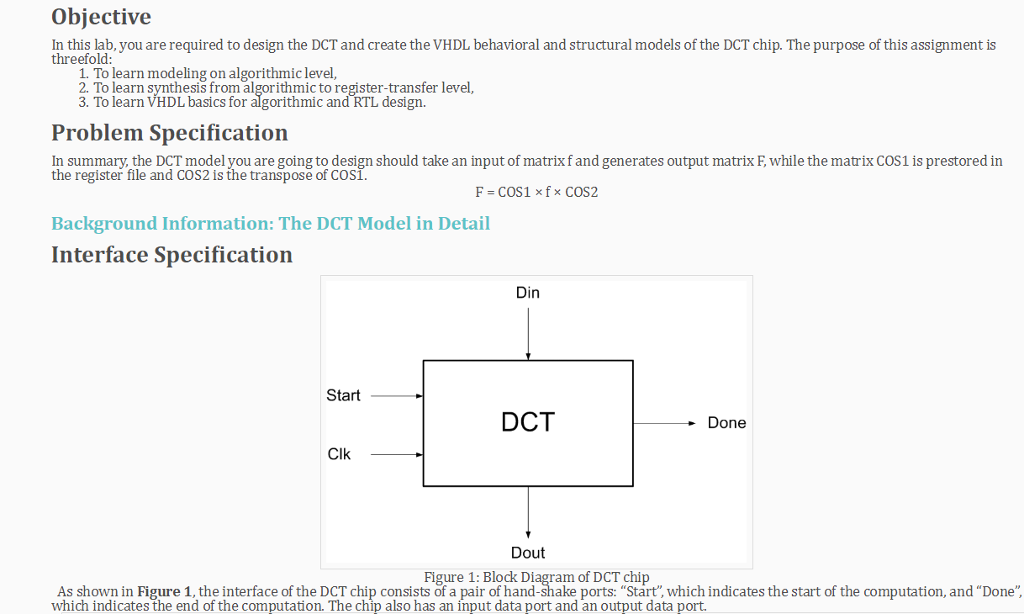
Objective In this lab, you are required to design the DCT and create the VHDL behavioral and structural models of the DCT chip. The purpose of this assignment is threefold 1 To learn modeling on algorithmic level, 2. To learn synthesis from algorithmic to register-transfer level 3. To learn VHDL basics for algorithmic and RTL design. Problem Specification In summary, the DCT model you are going to design should take an input of matrixf and generates output matrix F, while the matrix COS1 is prestored in the register file and COS2 is the transpose of COS Background Information: The DCT Model in Detail Interface Specification Din Start DCT - Done Clk Dout Figure 1: Block Diagram of DCT chip As shown in Figure 1, the interface of the DCT chip consists of a pair of hand-shake ports: "Start, which indicates the start of the computation, and "Done which indicates the end of the computation. The chip also has an input data port and an output data port. Objective In this lab, you are required to design the DCT and create the VHDL behavioral and structural models of the DCT chip. The purpose of this assignment is threefold 1 To learn modeling on algorithmic level, 2. To learn synthesis from algorithmic to register-transfer level 3. To learn VHDL basics for algorithmic and RTL design. Problem Specification In summary, the DCT model you are going to design should take an input of matrixf and generates output matrix F, while the matrix COS1 is prestored in the register file and COS2 is the transpose of COS Background Information: The DCT Model in Detail Interface Specification Din Start DCT - Done Clk Dout Figure 1: Block Diagram of DCT chip As shown in Figure 1, the interface of the DCT chip consists of a pair of hand-shake ports: "Start, which indicates the start of the computation, and "Done which indicates the end of the computation. The chip also has an input data port and an output data port
Step by Step Solution
There are 3 Steps involved in it
1 Expert Approved Answer
Step: 1 Unlock

Question Has Been Solved by an Expert!
Get step-by-step solutions from verified subject matter experts
Step: 2 Unlock
Step: 3 Unlock