

Question: NEED IT ASAP!!! USING BSL and Jump and Label instructions! Design a ladder diagram on logixpro! Subroutines (SBR) can be used to redirect PLC scanning
NEED IT ASAP!!! USING BSL and Jump and Label instructions! Design a ladder diagram on logixpro!
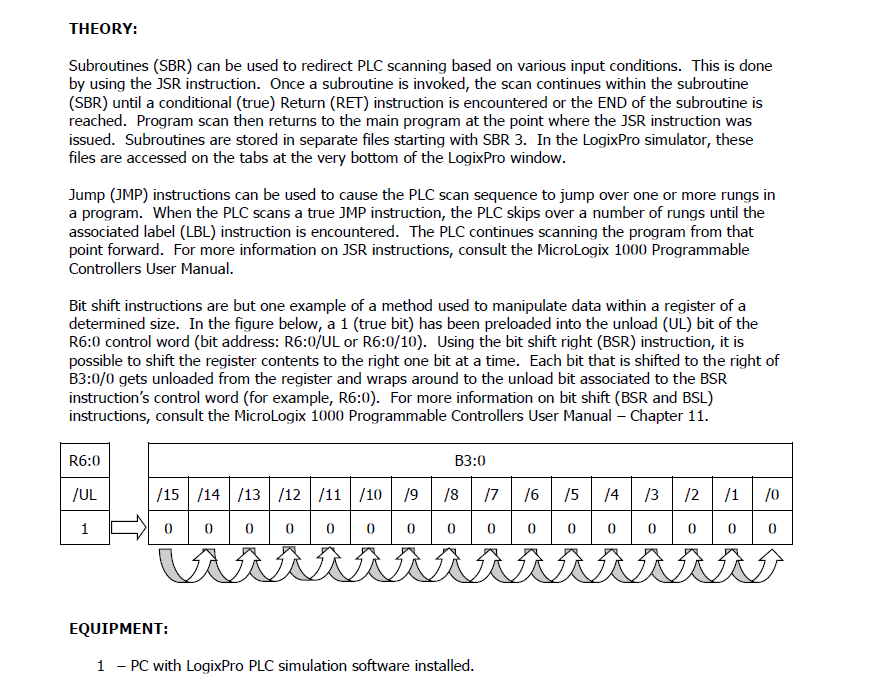
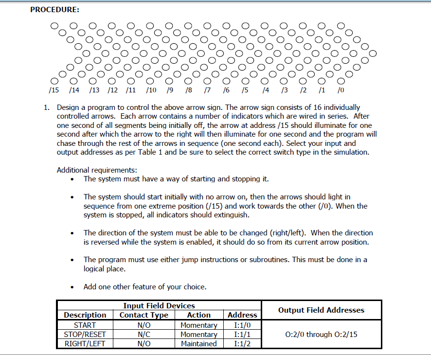
Subroutines (SBR) can be used to redirect PLC scanning based on various input conditions. This is done by using the JSR instruction. Once a subroutine is invoked, the scan continues within the subroutine (SBR) until a conditional (true) Return (RET) instruction is encountered or the END of the subroutine is reached. Program scan then returns to the main program at the point where the JSR instruction was issued. Subroutines are stored in separate files starting with SBR 3. In the LogixPro simulator, these files are accessed on the tabs at the very bottom of the LogixPro window. Jump (JMP) instructions can be used to cause the PLC scan sequence to jump over one or more rungs in a program. When the PLC scans a true JMP instruction, the PLC skips over a number of rungs until the associated label (LBL) instruction is encountered. The PLC continues scanning the program from that point forward. For more information on JSR instructions, consult the MicroLogix 1000 Programmable Controllers User Manual. Bit shift instructions are but one example of a method used to manipulate data within a register of a determined size. In the figure below, a 1 (true bit) has been preloaded into the unload (UL) bit of the R6:0 control word (bit address: R6:0/UL or R6:0/10). Using the bit shift right (BSR) instruction, it is possible to shift the register contents to the right one bit at a time. Each bit that is shifted to the right of B3:0/0 gets unloaded from the register and wraps around to the unload bit associated to the BSR instruction's control word (for example, R6:0). For more information on bit shift (BSR and BSL) instructions, consult the MicroLogix 1000 Programmable Controllers User Manual - Chapter 11. EQUIPMENT: 1 - PC with LogixPro PLC simulation software installed. 1. Design a program to control the above arrow sign. The arrow sign consists of 16 individually controlled arrows. Each arrow contains a number of indicators which are wired in series. After one second of all segments being initially off, the arrow at address / 15 should illuminate for one second after which the arrow to the right will then illuminate for one second and the program will chase through the rest of the arrows in sequence (one second each). Select your input and output addresses as per Table 1 and be sure to select the correct switch type in the simulation. Additional requirements: - The system must have a way of starting and stopping it. - The system should start initially with no arrow on, then the arrows should light in sequence from one extreme position (/15) and work towards the other (/0). When the system is stopped, all indicators should extinguish. - The direction of the system must be able to be changed (right/left). When the direction is reversed while the system is enabled, it should do so from its current arrow position. - The program must use either jump instructions or subroutines. This must be done in a logical place. - Add one other feature of your choice
Step by Step Solution
There are 3 Steps involved in it

Get step-by-step solutions from verified subject matter experts