

Question: NEED To DO THIS IN MATLAB. Engineers often measure the ration of two power measurements in decibles , or dB. The equation for the ratio
NEED To DO THIS IN MATLAB.
- Engineers often measure the ration of two power measurements in decibles, or dB. The equation for the ratio of two measurements in decibles is
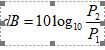
where P2 is the power level being measured and P1 is some reference level.
(Engineers have a special unit for dB power level with respect to 1 mW (milli Watt) reference: dBm )
- Assume that the reference power level P1 is 1 milliwatt (1 mW), and write a program that accepts an input power P2 of 10 Watts and converts it into dB with respect to the 1 mW reference level.
- Create a vector of power P2 from 1:100. Write a program that creates a plot of power P2 in watts verses power in dBm with respect to a 1 mW reference level. Create both a linear x y plot and a log-linear x y plot.
- Assume that the reference power level P1 is 1 watt (1 W), and write a program that calculates the decibel level corresponding to power levels of P2 between 1 and 20 watts, in 0.5 steps. Plot the dB verses power curve on a log - linear graph.
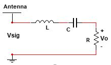
- A Radio Receivers is an RLC tuned circuit consisting of a resistor, inductor and a capacitor all connected in series. The circuit is connected to an external antenna and ground. This tuned circuit shown in figure allows the radio to select a specific radio station out of all stations transmitting on the AM band. At the resonant frequency of the circuit, all of the signal voltage Vsig appears across the load resistor R. In other words at the resonant frequency the radio receiver receives its strongest signal. The inductor and capacitor impedances
 , and
, and  , at the resonant frequency cancels (since equal and opposite to each other) resulting ZL+ Zc=0. The resonant frequency of the LC circuit is given by the equation as
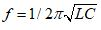 , where
  , L is the inductance in henrys (H), and Cm is the capacitance in farads (F).
Write a matlab program to calculate the resonant frequency of the above radio receiver for specific values of inductor and capacitor. Test your program for L= 0.1 mH and C= 0.25 nF.
dB = 10log10 ZL=1@L Antenna L C Vsig
Step by Step Solution
There are 3 Steps involved in it
1 Expert Approved Answer
Step: 1 Unlock

Question Has Been Solved by an Expert!
Get step-by-step solutions from verified subject matter experts
Step: 2 Unlock
Step: 3 Unlock