

Question: Objective: Design a controller for the heading control of the aircraft system represented by the block diagram shown in figure 1. a) Determine the
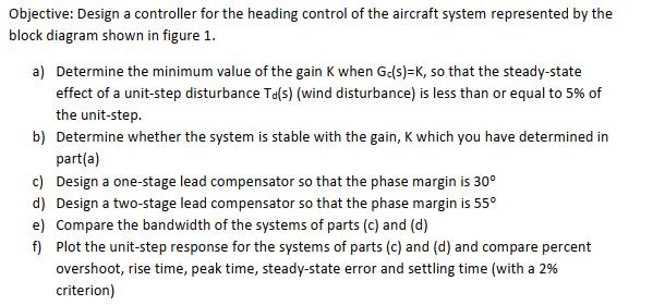
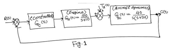
Objective: Design a controller for the heading control of the aircraft system represented by the block diagram shown in figure 1. a) Determine the minimum value of the gain K when Gc(s)-K, so that the steady-state effect of a unit-step disturbance Ta(s) (wind disturbance) is less than or equal to 5% of the unit-step. b) Determine whether the system is stable with the gain, K which you have determined in part(a) c) Design a one-stage lead compensator so that the phase margin is 30 d) Design a two-stage lead compensator so that the phase margin is 55 e) Compare the bandwidth of the systems of parts (c) and (d) f) Plot the unit-step response for the systems of parts (c) and (d) and compare percent overshoot, rise time, peak time, steady-state error and settling time (with a 2% criterion) R(S) (controller G(S) (Engine) Ge(s) = 160 S+10 Fig. 1 (Arcraft dynamics) 40 = s(s+20)
Step by Step Solution
3.34 Rating (151 Votes )
There are 3 Steps involved in it
a To determine the minimum value of the gain K you need to analyze the openloop transfer function of the system and evaluate the steadystate response ... View full answer

Get step-by-step solutions from verified subject matter experts