

Question: Objectives: Learn how to represent hardware combinational logic, including adders, in truth tables and logic equations, how to minimize logic using a Karnaugh map, and
Objectives: Learn how to represent hardware combinational logic, including adders, in truth tables and logic equations, how to minimize logic using a Karnaugh map, and how to represent and test hardware logic using the Verilog hardware description language and simulator. Submit your file through the Blackboard Assignment Portal for this class.
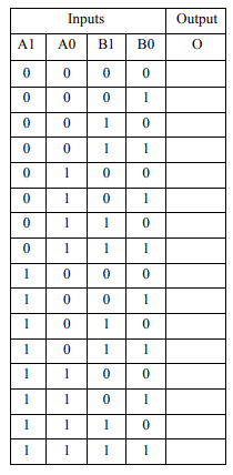
1. Design a comparator that takes four bits (A1, A0, B1, B0) as input and produces one bit (O) as output. O is 1 if and only if the binary value of A1A0 is less than the B1B0 when both pairs of bits are regarded as 2-bit unsigned integers.
(a) Complete the following truth table.
(b) Write the sum-of-product form for the output O without any simplification.
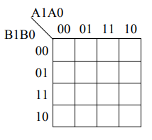
(c) Simplify the equation using a Karnaugh map.
d) Write the Verilog module for this circuit called module HW8P1 (A1, A0, B1, B0, O).
(e) Verilog code has been provided for this problem in the directory (not web page) at gaitrosd/cda3100_files in the file hw8.v with an empty HW8P1 module. Fill in this module with your solution above and run the simulation showing the waveform with only the signals relevant to this problem. In other words, print the waveform showing only the A1, A0, B1, B0, and O signals and turn in the printout with the rest of your assignment.
Inputs Al AO BBO Output
Step by Step Solution
There are 3 Steps involved in it

Get step-by-step solutions from verified subject matter experts