

Question: Overall component setup F 1 = 1 5 0 N F 2 = 1 3 0 N L 1 = 6 0 m m L
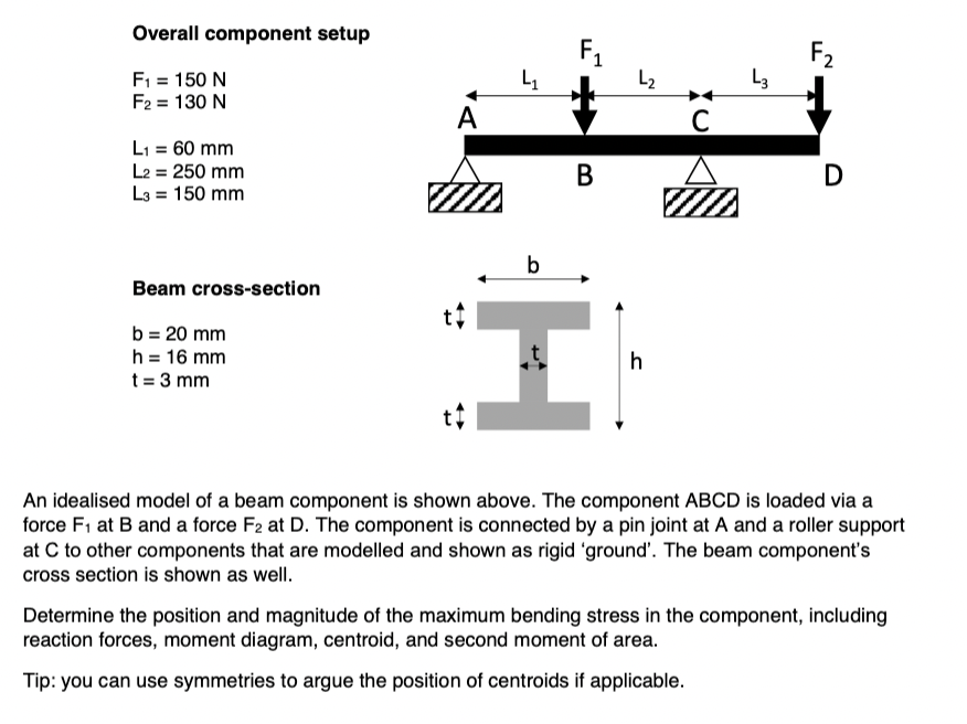
Overall component setup
Beam crosssection
An idealised model of a beam component is shown above. The component ABCD is loaded via a
force at and a force at The component is connected by a pin joint at A and a roller support
at to other components that are modelled and shown as rigid 'ground'. The beam component's
cross section is shown as well.
Determine the position and magnitude of the maximum bending stress in the component, including
reaction forces, moment diagram, centroid, and second moment of area.
Tip: you can use symmetries to argue the position of centroids if applicable.
Step by Step Solution
There are 3 Steps involved in it
1 Expert Approved Answer
Step: 1 Unlock

Question Has Been Solved by an Expert!
Get step-by-step solutions from verified subject matter experts
Step: 2 Unlock
Step: 3 Unlock